Systems and methods for high-dynamic range imaging

a high-dynamic range, imaging technology, applied in the field of high-dynamic range (hdr) imaging, can solve the problems of limited brightness range, muted or dull captured ldr or sdr image,

Active Publication Date: 2019-05-09
QUALCOMM INC
View PDF5 Cites 25 Cited by
  • Summary
  • Abstract
  • Description
  • Claims
  • Application Information

AI Technical Summary

Benefits of technology

[0005]Aspects of the present disclosure relate to systems and methods for generating High-Dynamic-Range (HDR) images. In some example implementations, a device may include a camera, one or more processors, and a memory. The memory may include instructions that, when executed by the one or more processors, cause the device to determine, from a preview image captured with an initial exposure value by the camera, a first exposure value for capturing a reference image, and determine a second exposure value for capturing a first non-reference image, wherein the second exposure value is based on a difference between the initial exposure value and the first exposure value. Execution of the instructions may further cause the device to capture the reference image using the first exposure value, to capture the first non-reference image using the second exposure value, and to blend the reference image and the first non-reference image to generate an HDR image.

Problems solved by technology

Many devices capture an LDR or SDR image using an automatically determined exposure value (e.g., an auto-exposure (AE) setting) and an undesirably limited range of brightness captured for the captured image.
For example, although a person is able to perceive a large range of brightness and light effects of a scene (such as shadows and color contrasts), a captured LDR or SDR image may appear muted or dull because of its limited range of brightness.

Method used


Image

  • Systems and methods for high-dynamic range imaging
  • Systems and methods for high-dynamic range imaging
  • Systems and methods for high-dynamic range imaging

Examples


Embodiment Construction

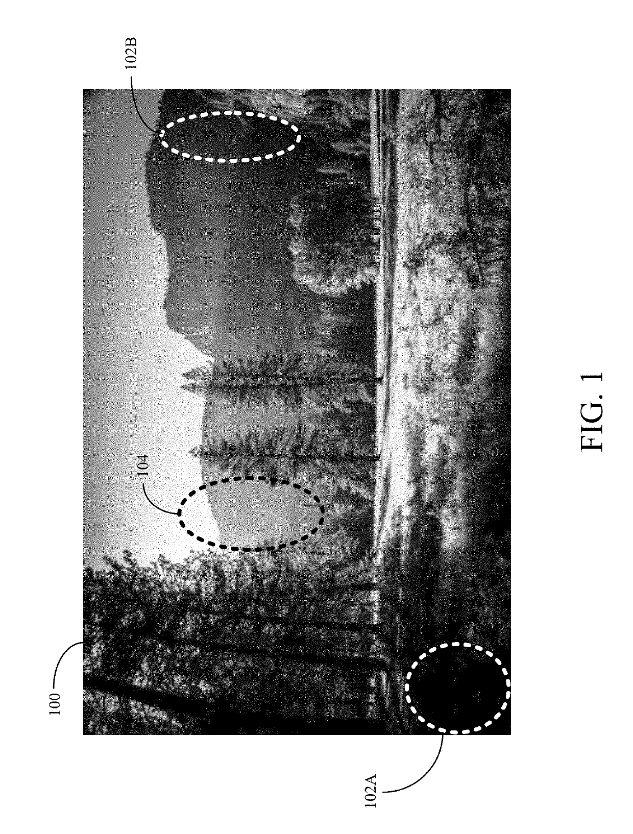
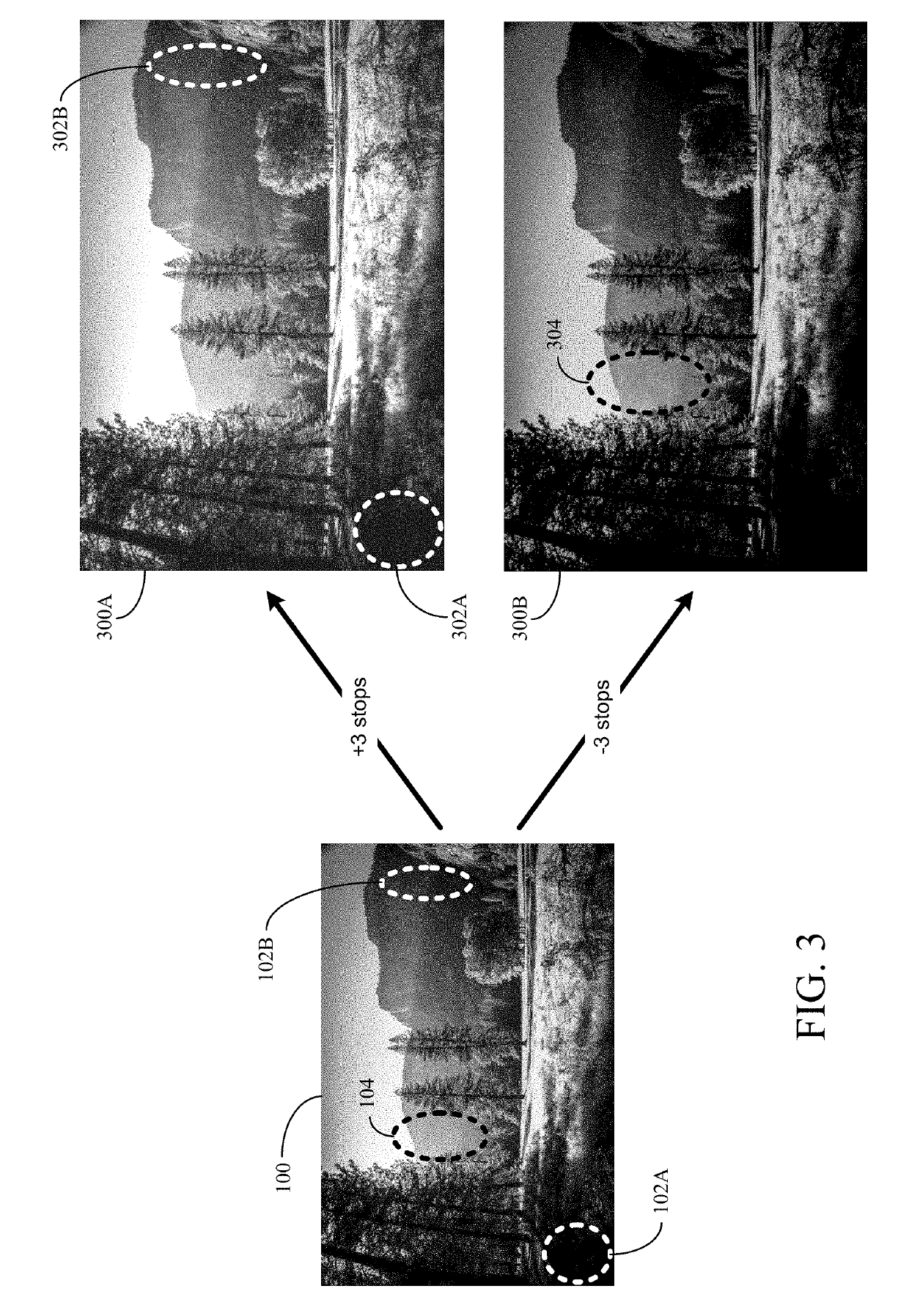
[0024]Aspects of the present disclosure may be used for generating HDR images. In some implementations, a device may capture multiple LDR or SDR images having different ranges of brightness, and then blend the multiple captured images to generate an HDR image. By blending the multiple captured images having different ranges of brightness, the resulting HDR image may have a larger range of brightness than conventional LDR or SDR images. In the following description, a single image captured using a camera sensor's standard or limited range of brightness is referred to as a LDR image. However, the term “LDR image” is for explanation purposes and is not intended to limit aspects of the disclosure. For example, a LDR image may be any image having a range of brightness that is than the range of brightness for an associated HDR image.

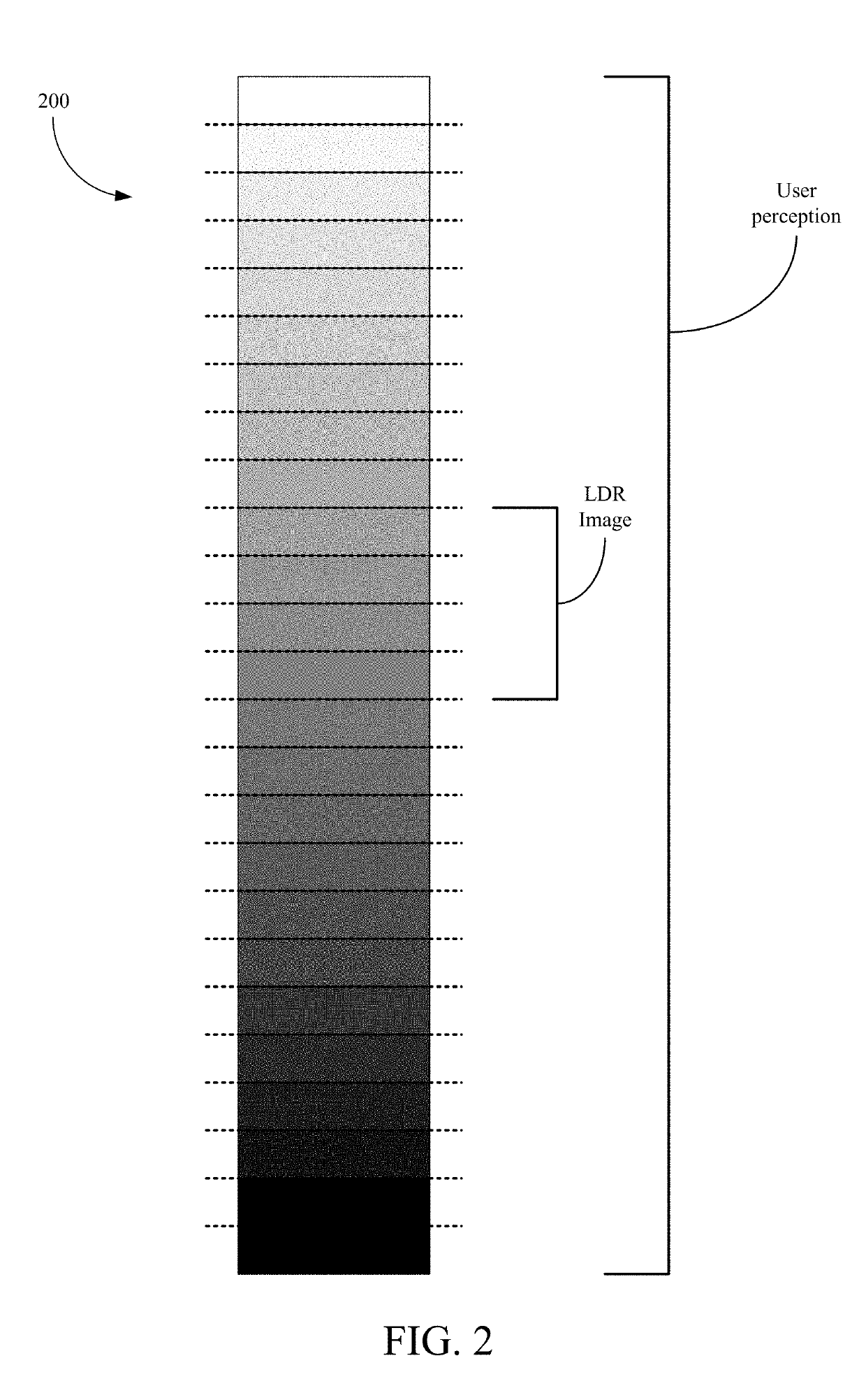
[0025]A digital camera sensor typically captures a limited range of brightness for a LDR image. To capture different ranges of brightness for multiple LDR ima...


PUM


Abstract

Aspects of the present disclosure relate to systems and methods for generating High-Dynamic Range (HDR) images. An example device may include a camera, one or more processors, and a memory. The memory may include instructions that, when executed by the one or more processors, cause the device to determine, from a preview image captured with an initial exposure value by a camera, a first exposure value for capturing a reference image, and a second exposure value for capturing a first non-reference image, wherein the second exposure value is based on a difference between the initial exposure value and the first exposure value. Execution of the instructions may further cause the device to capture the reference image using the first exposure value, capture the first non-reference image using the second exposure value, and blend the reference image and the first non-reference image in generating an HDR image.

Description

TECHNICAL FIELD[0001]This disclosure relates generally to systems for image capture devices, and specifically to high-dynamic range (HDR) imaging.BACKGROUND OF RELATED ART[0002]Devices including or coupled to one or more digital cameras use a camera sensor to capture light information for generating digital images. Camera sensors for digital cameras typically capture a limited range of brightness or light intensity when capturing an image frame of a scene. A conventional image captured with a limited or standard range of brightness is called a limited-dynamic range (LDR) image or a standard-dynamic range (SDR) image.[0003]Many devices capture an LDR or SDR image using an automatically determined exposure value (e.g., an auto-exposure (AE) setting) and an undesirably limited range of brightness captured for the captured image. For example, although a person is able to perceive a large range of brightness and light effects of a scene (such as shadows and color contrasts), a captured L...

Claims


Application Information

Patent Timeline
Patent Type & Authority Applications(United States)
IPC IPC(8): G06F3/14G09G5/14H04N5/232H04N5/235G06T5/00
CPCG06F3/1454G09G5/14H04N5/23248H04N5/2355G06T5/009G06T2207/20208G06T5/50G06T2207/10144G06T2207/20221H04N23/741H04N23/68
Inventor BAGARIA, LUCKYSRIVASTAVA, NITIN
Owner QUALCOMM INC
Why Eureka
Try Eureka