Bass reflex port and acoustic device

a bass reflex port and acoustic technology, applied in the direction of transducer details, electrical transducers, electrical apparatus, etc., can solve the problem of abnormal sound generated by the bass reflex port, and achieve the effect of preventing the growth of eddies, reducing abnormal noise generated due to the air flowing in the bass reflex port, and reducing abnormal nois

Active Publication Date: 2019-05-09
YAMAHA CORP
View PDF0 Cites 1 Cited by
  • Summary
  • Abstract
  • Description
  • Claims
  • Application Information

AI Technical Summary

Benefits of technology

[0010]With the bass reflex port according to the present invention, multiple regions with different viscous resistances are provided in a circumferential direction of an inner wall surface, and therefore the viscous resistance in the tube axis direction of the moving air and the inner wall surface changes along the circumferential direction. With the present bass reflex port, the amount of movement of the air that passes through the inner wall surface of the tube body differs in the multiple regions, and therefore the positions and timings at which eddies occur differ in these regions. That is, in the present bass reflex port, the positions and timings at which eddies occur differ in the circumferential direction. In this manner, the positions and timings at which the eddies occur are dispersed without being concentrated in the circumferential direction, and therefore in the present bass reflex port, the eddies can be prevented from growing, and the abnormal noise generated due to the eddies can be reduced. That is, according to the acoustic device including the present bass reflex port, the abnormal noise that occurs due to the air flowing in the bass reflex port can be reduced.
[0011]With the techniques disclosed in Patent Literatures 1 and 2, the positions and timings at which the eddies occur are not dispersed in the circumferential direction. In contrast to this, with the present bass reflex port, the positions and timings at which the eddies occur are dispersed in the circumferential direction as described above, and thus it is possible to prevent the eddies from growing. For this reason, according to the present bass reflex port, compared to the bass reflex ports disclosed in Patent Literatures 1 and 2, abnormal sound that is generated from the bass reflex port due to air flowing in the bass reflex port can be sufficiently reduced.

Problems solved by technology

With a bass reflex speaker, abnormal sound (noise) caused by the bass reflex port is generated.

Method used


Image

  • Bass reflex port and acoustic device
  • Bass reflex port and acoustic device
  • Bass reflex port and acoustic device

Examples


first embodiment

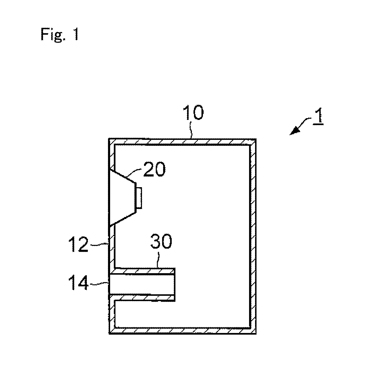
[0037]FIG. 1 is a cross-sectional view showing a configuration of an acoustic device 1 including a bass reflex port 30, which is a first embodiment of the present invention. The acoustic device 1 is a device that emits sound corresponding to an acoustic signal supplied from an external apparatus, and specifically is a bass reflex speaker. The acoustic device 1 includes an enclosure 10, which is the housing of the acoustic device 1, a speaker unit 20 composed of a vibration plate, a voice coil, and the like, and a bass reflex port 30.

[0038]The enclosure 10 is a hollow structural body (typically a cuboid) constituted by multiple plate materials. The speaker unit 20 is fixed to a plate material 12 among the multiple plate materials constituting the enclosure 10. The plate material 12 functions as a baffle surface. A circular opening 14 penetrating through the plate material 12 is provided in the plate material 12. The enclosure 10 of the present embodiment is constituted by multiple pl...

second embodiment

[0054]FIG. 6 is a development view in which a bass reflex port 30A, which is a second embodiment of the present invention, is opened by cutting the wall surface of the bass reflex port 30A in the tube axis direction. The bass reflex port 30A of the present embodiment is attached to an acoustic device, similarly to the bass reflex port 30 of the first embodiment.

[0055]The bass reflex port 30A differs from the bass reflex port 30 of the first embodiment in that it includes multiple recessed portions 34A and multiple recessed portions 35A instead of the sheet-like members 32. The recessed portions 34A and 35A are round recesses provided on the inner wall surface of the bass reflex port 30. The sizes (specifically, the diameters and depths) of the recessed portions 34A are larger than the sizes of the recessed portions 35A.

[0056]With the bass reflex port 30A, the multiple recessed portions 34A are provided on a portion in the circumferential direction of the inner wall surface, and the ...

third embodiment

[0065]FIG. 8 is a transparent side view showing a configuration of a bass reflex port 30B, which is a third embodiment of the present invention. The bass reflex port 30B of the present embodiment is attached to an acoustic device, similarly to the bass reflex port 30 of the first embodiment.

[0066]Both end portions of the bass reflex port 30B have flare shapes in which the surface areas of regions surrounded by the inner wall surface of the bass reflex port 30B expand toward the opening ends. The central portion of the bass reflex port 30B has a straight tube shape in which the area of the region surrounded by the inner wall surface of the bass reflex port 30B is kept approximately constant along the tube axis.

[0067]With the bass reflex port 30 of the first embodiment, the sheet-like members 30 were provided over the entire length along the tube axis. In contrast to this, the bass reflex port 30B of the present embodiment is provided with the sheet-like members 32B at portions in the...


PUM


Abstract

An acoustic device includes an enclosure and a bass reflex port that includes a tube body. An inner wall surface of the tube body includes multiple regions in which viscous resistances in a tube axis direction of moving air and the inner wall surface are different. The multiple regions are provided along a circumferential direction of the inner wall surface. The tube body is attached to an opening area in the enclosure.

Description

BACKGROUNDTechnical Field[0001]The present invention relates to a bass reflex port and an acoustic device such as a bass reflex speaker.Background Art[0002]A bass reflex speaker that enhances the volume of the low-pitch range using sound reflected from a speaker unit toward a rear surface has conventionally been proposed. With a bass reflex speaker, a bass reflex port that causes the interior and exterior of a housing (enclosure) to be in communication is installed. With a bass reflex speaker, abnormal sound (noise) caused by the bass reflex port is generated. In view of this, various techniques for reducing the abnormal sound from the bass reflex port have been proposed.[0003]Patent Literature 1 discloses a bass reflex port with an inner wall surface on which multiple ribs are provided. With this bass reflex port, multiple ribs formed over the entire length of the bass reflex port are arranged in the circumferential direction of the bass reflex port such that the length direction o...

Claims


Application Information

Patent Timeline
Patent Type & Authority Applications(United States)
IPC IPC(8): H04R1/28H04R1/02
CPCH04R1/2819H04R1/025H04R1/2826H04R1/2849H04R1/02
Inventor MIKI, AKIRAONITSUKA, HIROFUMIUCHIDA, KATSUYA
Owner YAMAHA CORP
Why Eureka
Try Eureka