Audio circuit

a technology of audio circuits and circuits, applied in the direction of transducer details, electrical transducers, electrical apparatus, etc., can solve the problems of difficult to correct the variation in characteristics of such arrangements, and achieve the effects of improving sound quality, degrading sound quality, and improving sound quality

Active Publication Date: 2019-05-09
ROHM CO LTD
View PDF2 Cites 4 Cited by
  • Summary
  • Abstract
  • Description
  • Claims
  • Application Information

AI Technical Summary

Benefits of technology

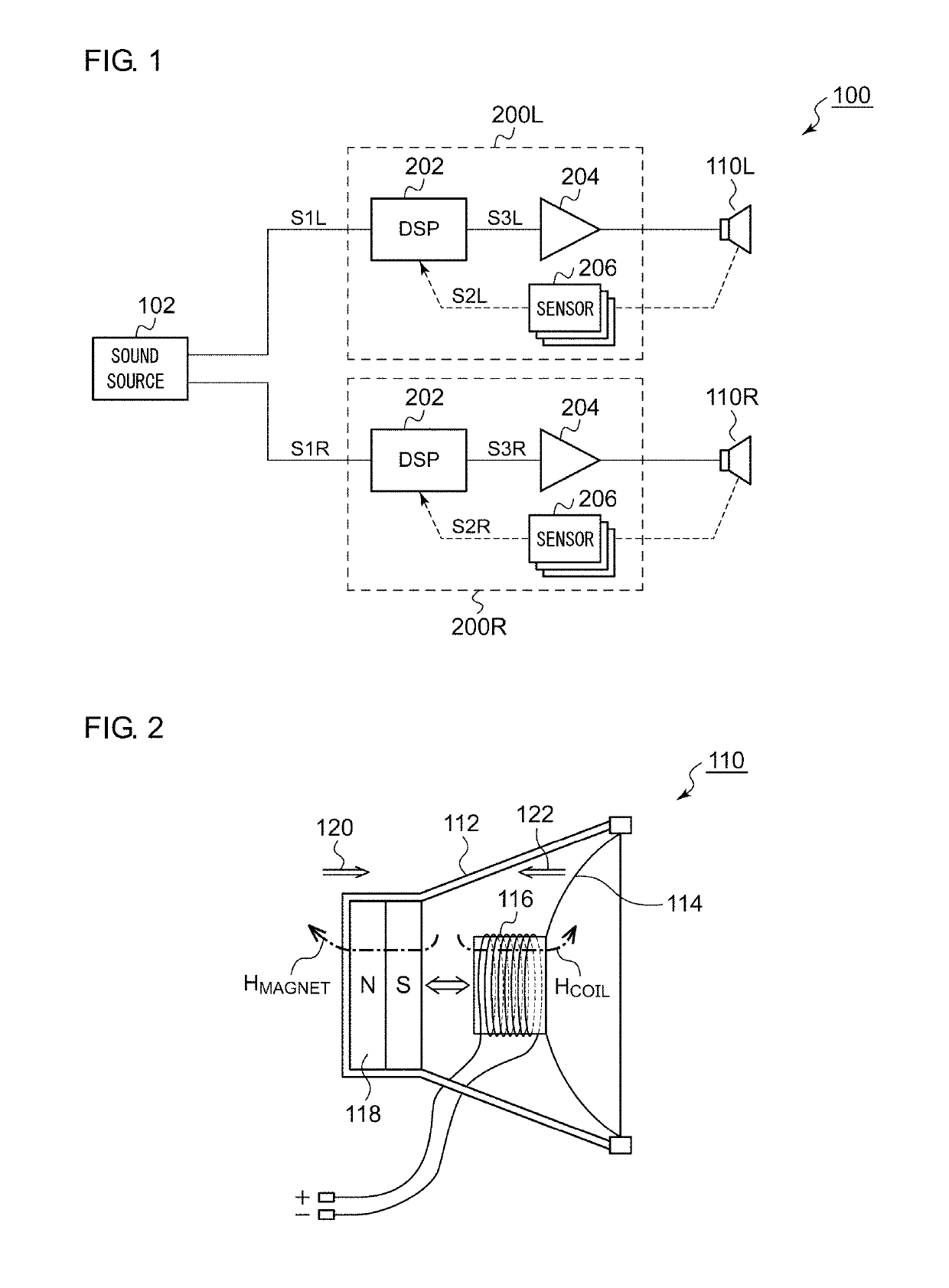
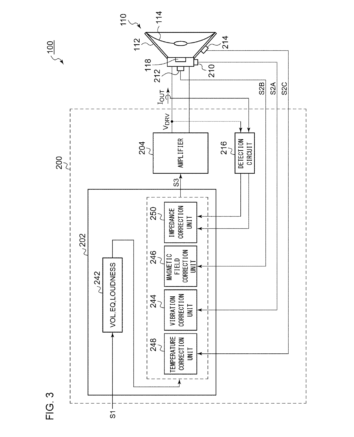
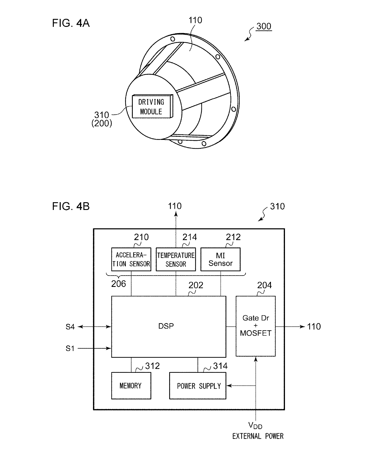
[0014]When vibration (which is referred to as “disturbance vibration”) occurs in the housing of the speaker itself in a direction that is orthogonal to the face of the vibration plate, this is equivalent to an operation as if the vibration plate were driven due to the disturbance vibration. This leads to degradation in the sound quality. With this embodiment, by vibrating the vibration plate with a phase that is the opposite of that of the disturbance vibration, this arrangement is capable of canceling out the effects of the disturbance vibration, thereby providing improved sound quality.
[0015]Also, at least one sensor may be a magnetic sensor structured to detect the magnetic field generated by the speaker. There is a difference in the magnetic field generated by the magnet between the speakers. Furthermore, the magnetic field varies due to aging degradation. With a multi-channel audio system, such a difference in the magnetic field between the speakers manifests as a difference in the output between the multiple speakers, which is a cause of degraded sound quality. In order to solve such a problem, by correcting the audio signal for each channel according to the magnetic field, this arrangement is capable of suppressing such a difference between the channels, thereby providing improved sound quality.
[0016]Also, at least one sensor may be a temperature sensor structured to detect the temperature of the speaker. With a multi-channel audio system, a difference in the temperature between the speakers manifests as a difference in the output between the multiple speakers, which becomes a cause of degraded sound quality. In order to solve such a problem, by correcting the audio signal for each channel according to the temperature, this arrangement is capable of suppressing such a difference between channels, thereby providing improved sound quality.
[0017]When the temperature is high, the signal processing unit may superimpose a low-frequency component outside the audible band on the audio signal. This arrangement is capable of cooling the speaker by means of aerodynamic effects.

Problems solved by technology

However, it is difficult for such an arrangement to correct variation in characteristics due to dynamic factors such as vibration applied to the speakers, temperature variation, aging degradation of the speakers, or the like.

Method used


Image

  • Audio circuit
  • Audio circuit
  • Audio circuit

Examples


Embodiment Construction

[0029]The invention will now be described based on preferred embodiments which do not intend to limit the scope of the present invention but exemplify the invention. All of the features and the combinations thereof described in the embodiment are not necessarily essential to the invention.

[0030]In the present specification, the state represented by the phrase “the member A is coupled to the member B” includes a state in which the member A is indirectly coupled to the member B via another member that does not substantially affect the electric connection between them, or that does not damage the functions of the connection between them, in addition to a state in which they are physically and directly coupled.

[0031]Similarly, the state represented by the phrase “the member C is provided between the member A and the member B” includes a state in which the member A is indirectly coupled to the member C, or the member B is indirectly coupled to the member C via another member that does no...


PUM


Abstract

An audio circuit drives a speaker. A DSP corrects an audio signal S1 according to the state of the speaker. An amplifier drives the speaker according to a corrected audio signal S3.

Description

CROSS-REFERENCE TO RELATED APPLICATION[0001]The present application claims priority under 35 U.S.C. § 119 to Japanese Patent Application No. 2017-167042, filed on Aug. 31, 2017, the entire contents of which are incorporated herein by reference.BACKGROUND OF THE INVENTION1. Field of the Invention[0002]The present invention relates to an audio circuit.2. Description of the Related Art[0003]In-vehicle audio apparatuses (car audio apparatuses) or home audio apparatuses are provided with multiple speakers arranged at different positions. In order to support high-quality audio reproduction operation, such multiple channels preferably have uniform characteristics.[0004]In recent years, accompanying advances in digital signal processing techniques, it has become possible to support correction processing to provide multiple channels with uniform characteristics. Specifically, a known audio signal (reference signal) is reproduced. The audio signal thus reproduced is acquired by means of a mic...

Claims


Application Information

Patent Timeline
Patent Type & Authority Applications(United States)
IPC IPC(8): H04R3/00H04R29/00
CPCH04R3/007H04R29/001H04R2499/13H04R3/08
Inventor MORITOKI, KENICHISAKAMOTO, MITSUAKI
Owner ROHM CO LTD
Why Eureka
Try Eureka