Early effect cancelling circuit, differential amplifier, linear regulator, and early effect canceling method

a technology of early effect and linear regulator, applied in the direction of amplifiers, amplifiers with semiconductor devices/discharge tubes, instruments, etc., can solve the problems of increasing the chip size ripple noise suppression, etc., to achieve wide mounting area, reduce noise, sound quality deterioration

Active Publication Date: 2006-08-31
MONTEREY RES LLC
View PDF9 Cites 4 Cited by
  • Summary
  • Abstract
  • Description
  • Claims
  • Application Information

AI Technical Summary

Benefits of technology

[0008] If current variation components due to Early effects are contained in the input current flowing in the current mirror circuit, it is a problem because current variation components directly appear in the output current of the current mirror circuit. In particular, when the current mirror circuit is used in linear regulator for sound source circuit, ripple noise may appear in output voltage of linear regulator, and sound quality may deteriorate. To prevent output of ripple noise from linear regulator, ripple noise may be suppressed by force by installing a filter composed of coil (or resistance) and capacitor in the output stage. But such filter uses capacitor, etc. and is wide in mounting area, and causes to increase the chip size.

Problems solved by technology

If current variation components due to Early effects are contained in the input current flowing in the current mirror circuit, it is a problem because current variation components directly appear in the output current of the current mirror circuit.
In particular, when the current mirror circuit is used in linear regulator for sound source circuit, ripple noise may appear in output voltage of linear regulator, and sound quality may deteriorate.
But such filter uses capacitor, etc. and is wide in mounting area, and causes to increase the chip size.

Method used


Image

  • Early effect cancelling circuit, differential amplifier, linear regulator, and early effect canceling method
  • Early effect cancelling circuit, differential amplifier, linear regulator, and early effect canceling method
  • Early effect cancelling circuit, differential amplifier, linear regulator, and early effect canceling method

Examples


first embodiment

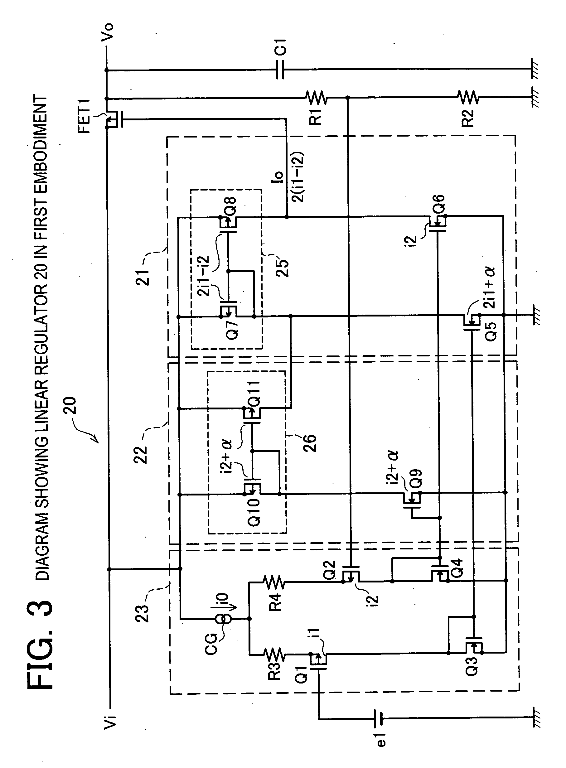
[0039] In the first embodiment, cancelation of Early voltage effects in driver circuit 21 is explained by referring to FIG. 3. The linear regulator 20 shown in FIG. 3 comprises a driver circuit 21, an Early voltage detector 22, an error amplifier 23, a main transistor FET1, a capacitor C1, and resistance elements R1 and R2. The linear regulator 20 receives an input voltage Vi, and sends out an output voltage Vo. The main transistor FET1 is a transistor for regulating the input voltage Vi, and issuing an output voltage Vo. The input voltage Vi is put in the source electrode of the main transistor FET1, and the output voltage Vo is issued from the drain electrode. An output terminal of the driver circuit 21 is connected to the control electrode (gate) of the main transistor FET1. The capacitor C1 is a capacitor for smoothing the output voltage Vo.

[0040] The driver circuit 21 is a circuit for driving the main transistor FET1 by receiving the output of the error amplifier 23. The driver...

second embodiment

[0073] A linear regulator 20a in the second embodiment is explained by referring to FIG. 5. Early voltage effects appear in inverting input side transistor Q1 to which reference voltage e1 of error amplifier 23 is connected, and noninverting input side transistor Q2 receiving divided voltage of output voltage Vo. Hence, the linear regulator 20a has first auxiliary error amplifier 24 and second auxiliary error amplifier 34 in parallel to each input. Hence, this is a method of preventing Early voltage effects from appearing in output current of error amplifier 23.

[0074] The first auxiliary error amplifier 24 and second auxiliary error amplifier 34 are a differential input current mirror circuit composition having a same element configuration as the error amplifier 23. The first auxiliary error amplifier 24 is connected in parallel to the inverting input side transistor Q1 of the error amplifier 23, and second auxiliary error amplifier 34 is connected in parallel to the noninverting in...


PUM


Abstract

In an input transistor of current mirror circuit, it is intended to prevent the current generated by Early effects from appearing in the output current of the current mirror circuit. Having an Early voltage detector 22 of same connection and structure as a driver circuit 21, and connected in parallel to the driver circuit 21, the current flowing in input transistor Q9 of the Early voltage detector 22 is detected. Output current (current IQ11) of Early voltage detector 22 is added to input current (current IQ5) of driver circuit 21. As a result, in input current (current IQ7) of current mirror circuit 25, current α due to Early voltage effects can be canceled. At the same time, current α due to Early voltage effects generated in input transistor Q5 of current mirror circuit 25 is prevented from appearing in output current (current IQ8) of current mirror circuit 25.

Description

CROSS-REFERENCE TO RELATED APPLICATIONS [0001] This application is based upon and claims the benefit of priority from the prior Japanese Patent Application No. 2005-051250 filed on Feb. 25, 2005, the entire contents of which are incorporated herein by reference. BACKGROUND OF THE INVENTION [0002] 1. Field of the Invention [0003] The present invention relates to Early effect canceling circuit and Early effect canceling method, and more particularly to circuit and method capable of preventing current generated by Early effect from appearing in output current of current mirror circuit. [0004] 2. Description of the Related Art [0005] If current variation components due to Early effects are contained in the input current flowing in the current mirror circuit, its effects directly appear in the output current of the current mirror circuit. Accordingly, this current mirror circuit is explained as an example of using in DC-DC converter of linear regulator system. [0006] In laptop and other ...

Claims


Application Information

Patent Timeline
Patent Type & Authority Applications(United States)
IPC IPC(8): G05F3/16G05F3/20
CPCG05F1/575H03F3/345H03F3/45273H03F2200/303H03F2200/91
Inventor KIZAKI, YOSHIHIROYASUKOUCHI, KATSUYUKIITO, HIDENOBU
Owner MONTEREY RES LLC
Why Eureka
Try Eureka