Minimally Invasive Bone Fracture Positioning Device

a positioning device and minimally invasive technology, applied in the field of minimally invasive bone fracture positioning devices, can solve the problems of increasing increasing the complication and operation time of surgery, and reducing so as to reduce the risk of operation and the burden on the patient's body

Active Publication Date: 2019-05-16
METAL INDS RES & DEV CENT
View PDF7 Cites 3 Cited by
  • Summary
  • Abstract
  • Description
  • Claims
  • Application Information

AI Technical Summary

Benefits of technology

[0005]To solve the above problems, an objective of the present invention is to provide a minimally invasive bone fracture positioning device that can proceed with p

Problems solved by technology

Thus, the complication and the operation time of the surgery will be increased, affecting

Method used


Image

  • Minimally Invasive Bone Fracture Positioning Device
  • Minimally Invasive Bone Fracture Positioning Device
  • Minimally Invasive Bone Fracture Positioning Device

Examples


Embodiment Construction

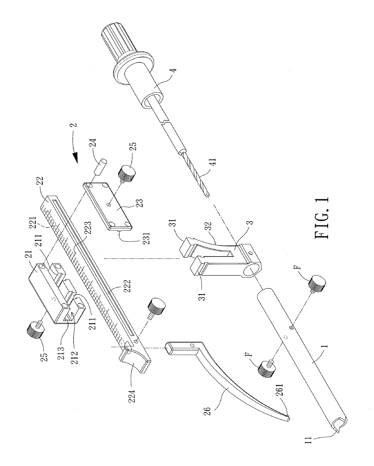
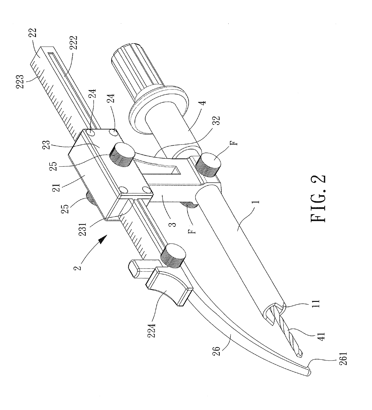
[0027]With reference to FIGS. 1 and 2, a minimally invasive bone fracture positioning device according to the present invention includes a sleeve 1, a movable unit 2, and a support 3. The support 3 is coupled to the sleeve 1 and the movable unit 2, such that the sleeve 1 is spaced from and parallel to the movable unit 2 by the support 3.

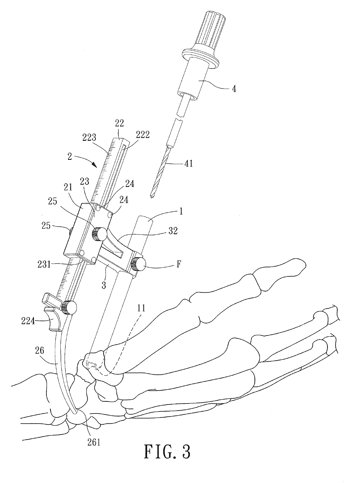
[0028]The sleeve 1 includes an alignment portion 11 at an end thereof and located on a longitudinal axis X of the sleeve 1. The alignment portion 11 can be a fixing member in the form of a hook, a claw, or a collar for mating with a shape of a surface of a bone. A therapeutic tool can be inserted into the sleeve 1 via the other end of the sleeve 1.

[0029]The movable unit 2 includes a block 21 having a first engaging portion 211 fixed to the support 3 and a track 22. The block 21 is slideably mounted to the track 22. In the embodiment shown, the block 21 includes a track groove 212 extending along the longitudinal axis X for slideably receiving the tra...


PUM


Abstract

A minimally invasive bone fracture positioning device includes a sleeve, a movable unit, and a support. The sleeve includes an alignment portion located on a longitudinal axis of the sleeve. The movable unit includes a positioning portion. The positioning portion is located on the longitudinal axis and is spaced from the alignment portion. The movable unit is mounted in a radial direction of the sleeve. The movable unit is slideable relative to the sleeve along the longitudinal axis. A support is coupled to the sleeve and the movable unit. The movable unit is spaced from the sleeve by the support.

Description

BACKGROUND1. Technical Field[0001]The present invention relates to a minimally invasive bone fracture positioning device and, more particularly, to a minimally invasive bone fracture positioning device that can be used through two small open wounds.2. Description of the Related Art[0002]When a bone has a serious fracture misalignment problem, it is necessary to implant a bone nail through an operation to assure reliable engagement of the fracture during the recovery period after accurate osteosynthesis. During a surgery including drilling a hole and implanting a bone nail, a bone fracture positioning device is firstly used to tightly clamp two ends of the fractured part of the bone to assure that the bone remains tight and accurate joining at the fracture while providing positioning and orientation functions to assist in the therapy.[0003]However, two ends of the above conventional bone fracture positioning device for clamping and positioning are coaxially moved and, thus, require i...

Claims


Application Information

Patent Timeline
IPC IPC(8): A61B17/88A61B17/64
CPCA61B17/8866A61B17/6408A61B17/8872A61B17/6416A61B17/66A61B2017/681A61B17/6466A61B17/1782
Inventor WANG, YUE-JUNCHANG, CHIH-HAOHUANG, SHIH-HUALIN, CHIH-LUNGTSAI, TUNG-LINTSENG, CHUN-CHIEHWENG, LI-WEN
Owner METAL INDS RES & DEV CENT
Why Eureka
Try Eureka