Vehicle

a technology for vehicles and exhaust ducts, applied in the field of vehicles, can solve the problems of vibration noise of the engine attenuated inside the exhaust duct, propagating through the muffler cover, etc., and achieve the effects of reducing noise leakage, reducing open/close deterioration, and discharging exhaust gas

Active Publication Date: 2019-05-16
YAMAHA MOTOR POWER PROD KK
View PDF0 Cites 2 Cited by
  • Summary
  • Abstract
  • Description
  • Claims
  • Application Information

AI Technical Summary

Benefits of technology

[0015]Further, preferably, the open / close member is opened to an amount in accordance with an exhaust gas pressure received by the open / close member. In this case, as the exhaust gas pressure (amount of exhaust gas) increases, the amount of opening of the open / close member increases. Therefore, when the engine is running at a slow speed (e.g., not greater than about 2500 rpm), the exhaust gas pressure (amount of exhaust gas) is small and the open / close member is half open, so it is possible to achieve both discharging of the exhaust gas and reducing noise leakage to outside of the vehicle. This structure is particularly effective when the vehicle is traveling at a constant speed.
[0016]Preferably, the vehicle further includes a cooling hole provided in the exhaust duct, and the cooling hole penetrates an inner circumferential surface and an outer circumferential surface of the exhaust duct downstream of, but adjacent to, the open / close member in its closed state. In this case, it is possible to cool the open / close member and therefore reduce deterioration of the open / close member due to heat.
[0017]According to preferred embodiments of the present invention, it is possible for vehicles to reduce sound leakage therefrom.

Problems solved by technology

Also, since the exhaust duct is connected to the muffler cover, a cooling wind from the muffler cover passes through the exhaust duct and is discharged from the opening, and noise propagating through the muffler cover such as vibration noise of the engine is attenuated inside the exhaust duct.

Method used


Image

  • Vehicle
  • Vehicle
  • Vehicle

Examples


Embodiment Construction

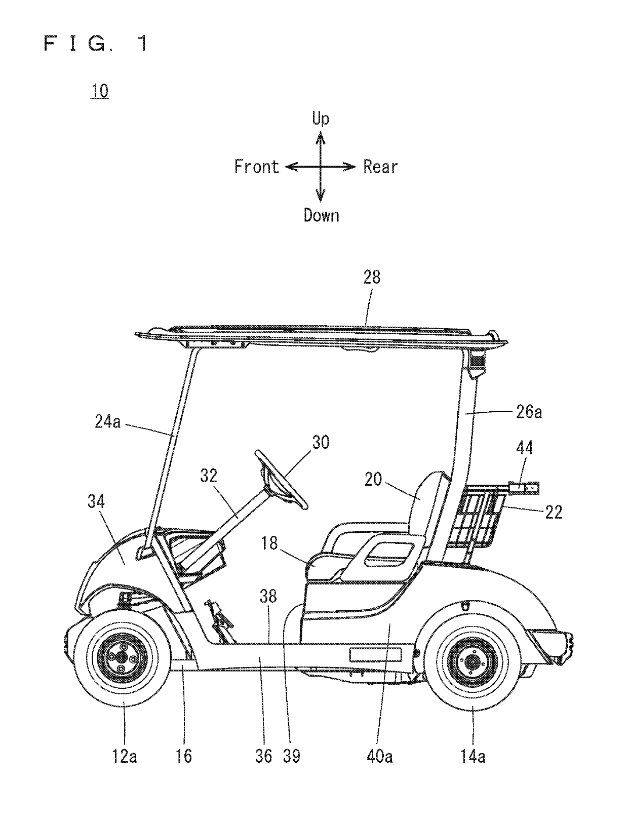
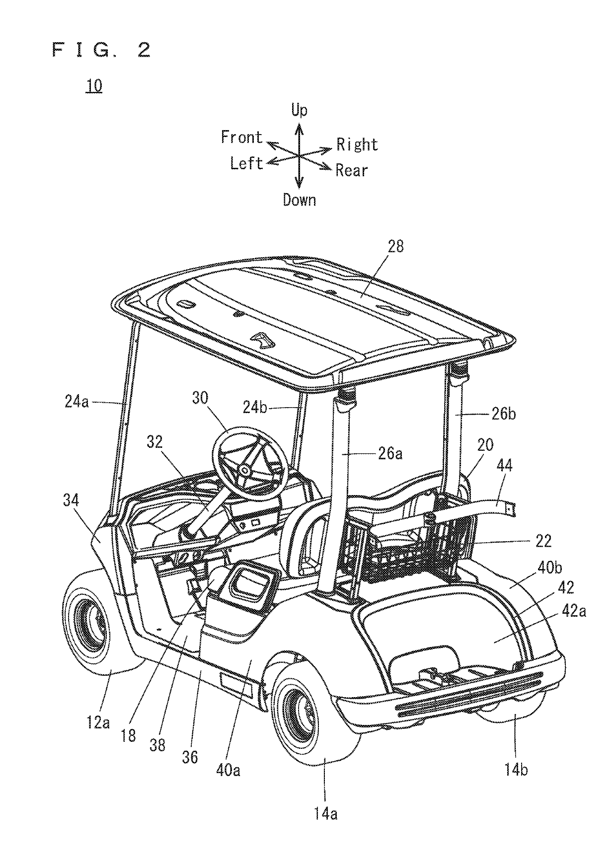
[0049]Hereinafter, preferred embodiments of the present invention will be described with reference to the drawings. Herein, description will be made in which a preferred embodiment of the present invention is applied to a golf car 10 as an example of a vehicle. It is noted that the terms front and rear, right and left, up and down as used in the following description are determined from the golf car driver's position on a seat 18 of the golf car 10, with the driver facing toward a steering wheel 30.

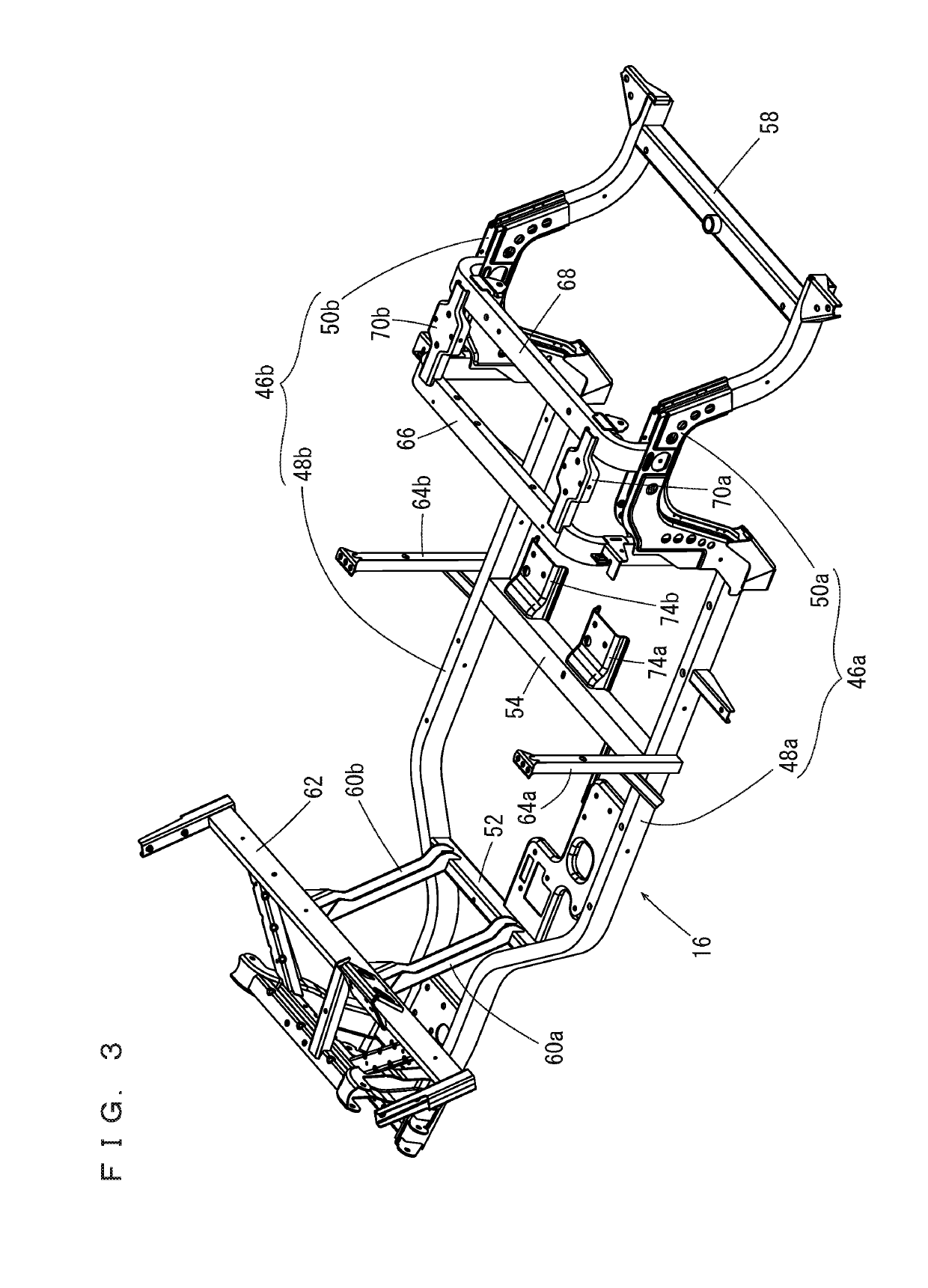
[0050]Referring to FIG. 1 and FIG. 2, the golf car 10 is, for example, a two-person golf car, and includes a pair of front wheels 12a, 12b (see FIG. 9), a pair of rear wheels 14a, 14b, and a frame 16. The pair of rear wheels 14a, 14b are located more rearward than the pair of front wheels 12a, 12b. The pair of front wheels 12a, 12b are supported rotatably at a front region of the frame 16. The pair of rear wheels 14a, 14b are supported rotatably at a rear region of the frame 16.

[0051]The ...


PUM


Abstract

A golf car includes an engine and a shroud that covers a cylinder body. The shroud communicates with a muffler cover, which covers a muffler. A silencer is provided at an outlet of the muffler. An elastic exhaust duct is connected to an exit end portion of the muffler cover. An undercover is located lower than the engine, and defines an underside of an engine room. The undercover includes an opening at a more rearward position than the muffler in a side view. The exhaust duct is routed above the undercover, includes a rearward end portion at the opening, and is fitted to the opening. Holders hold sound absorbing members on an inner circumferential surface of the exhaust duct.

Description

BACKGROUND OF THE INVENTION1. Field of the Invention[0001]The present invention relates to vehicles, and more specifically to a vehicle including an engine.2. Description of the Related Art[0002]JP-A 2005-7995 discloses an example of a conventional technique in this field. JP-A 2005-7995 discloses a small vehicle in which a drive unit is mounted at a rear region of a vehicle body frame via a sub-frame. In the small vehicle, the drive unit is composed of an engine and a transmission connected to the engine via a V-belt type automatic transmission device. A muffler is mounted on the left side of the vehicle and is connected to an engine cylinder via an exhaust pipe. At a lower end portion of the muffler, a generally L-shaped exhaust gas discharge pipe is connected, and the pipe is routed through a hole formed in a sound insulation board mounted on a lower portion of the sub-frame, and is brought to the outside. The exhaust gas passes through the pipe and then is discharged rearward fr...

Claims


Application Information

Patent Timeline
Patent Type & Authority Applications(United States)
IPC IPC(8): B60K13/04F01N1/24F01N13/20B62D21/18
CPCB60K13/04F01N1/24F01N13/20B62D21/183B60Y2200/23B60K2005/003B60G2300/07F01N1/00F01N2470/02B60Y2400/72
Inventor OBA, YUYAYOSHIKAWA, MAKOTOITO, TAKESHI
Owner YAMAHA MOTOR POWER PROD KK
Why Eureka
Try Eureka