
Projection system and image projection method

a projection system and image technology, applied in the field of projection system and image projection method, can solve the problems of difficult manual adjustment of users, difficult to achieve precise projection position, and complicated image correction function of known projection devi

Inactive Publication Date: 2019-05-16
CORETRONIC
View PDF15 Cites 5 Cited by
  • Summary
  • Abstract
  • Description
  • Claims
  • Application Information

AI Technical Summary

Benefits of technology

The invention is a projection system and method that can capture an image of the surface it is projecting onto. It then adjusts the image to match the user's needs. This allows for quick and automatic adjustment of the projection range, making it easier and more user-friendly.

Problems solved by technology

An image correction function of a known projection device is generally too complicated in operation, and the user has to make multiple adjustments to a projected image in order to match the projected image with a predetermined projection region, and manual adjustment of the user is always hard to achieve a precise projection position.

Method used


Image

  • Projection system and image projection method
  • Projection system and image projection method
  • Projection system and image projection method

Examples


Embodiment Construction

[0025]In the following detailed description of the preferred embodiments, reference is made to the accompanying drawings which form a part hereof, and in which are shown by way of illustration specific embodiments in which the invention may be practiced. In this regard, directional terminology, such as “top,”“bottom,”“front,”“back,” etc., is used with reference to the orientation of the Figure(s) being described. The components of the present invention can be positioned in a number of different orientations. As such, the directional terminology is used for purposes of illustration and is in no way limiting. On the other hand, the drawings are only schematic and the sizes of components may be exaggerated for clarity. It is to be understood that other embodiments may be utilized and structural changes may be made without departing from the scope of the present invention. Also, it is to be understood that the phraseology and terminology used herein are for the purpose of description an...


PUM


Abstract

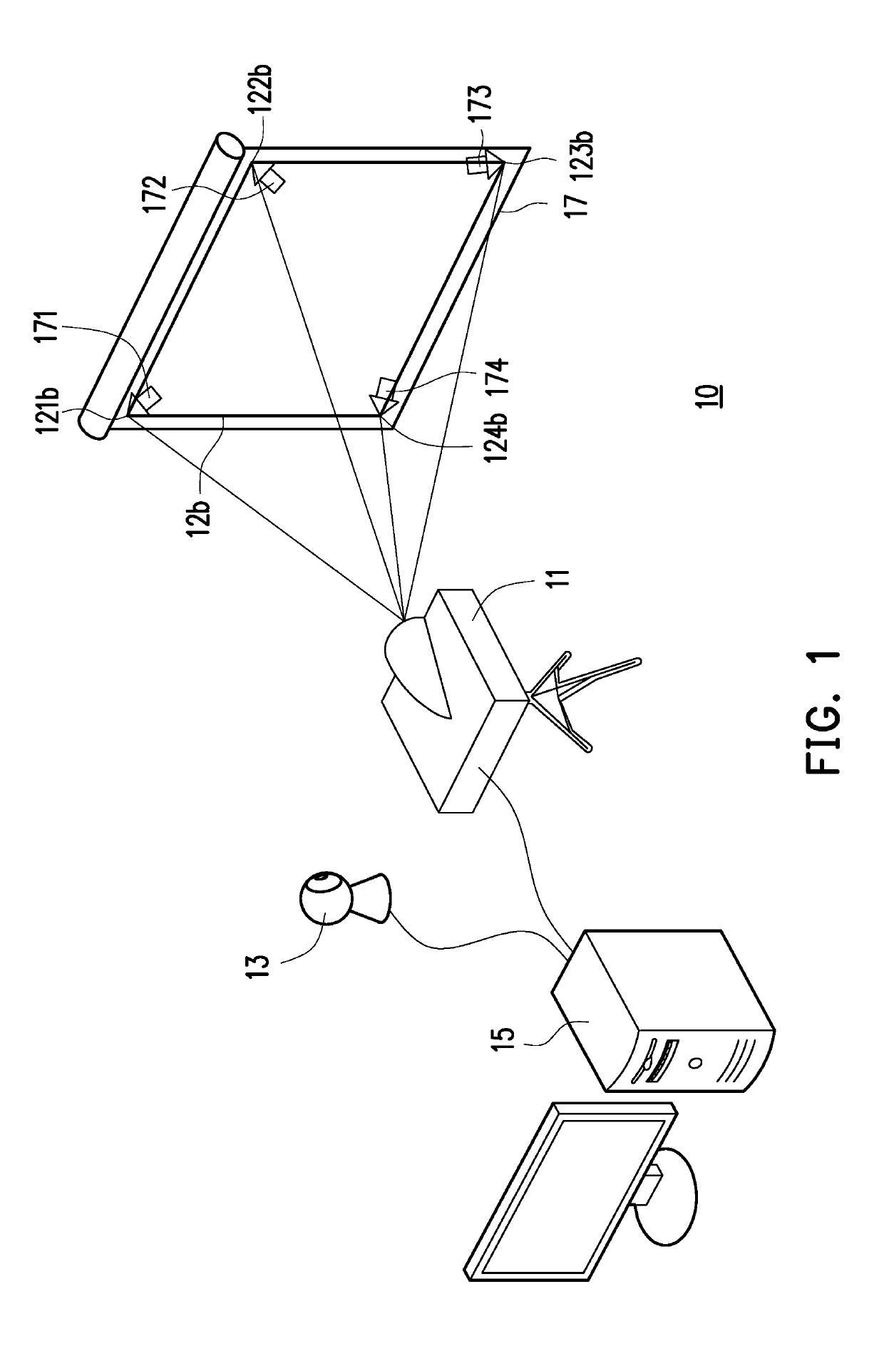
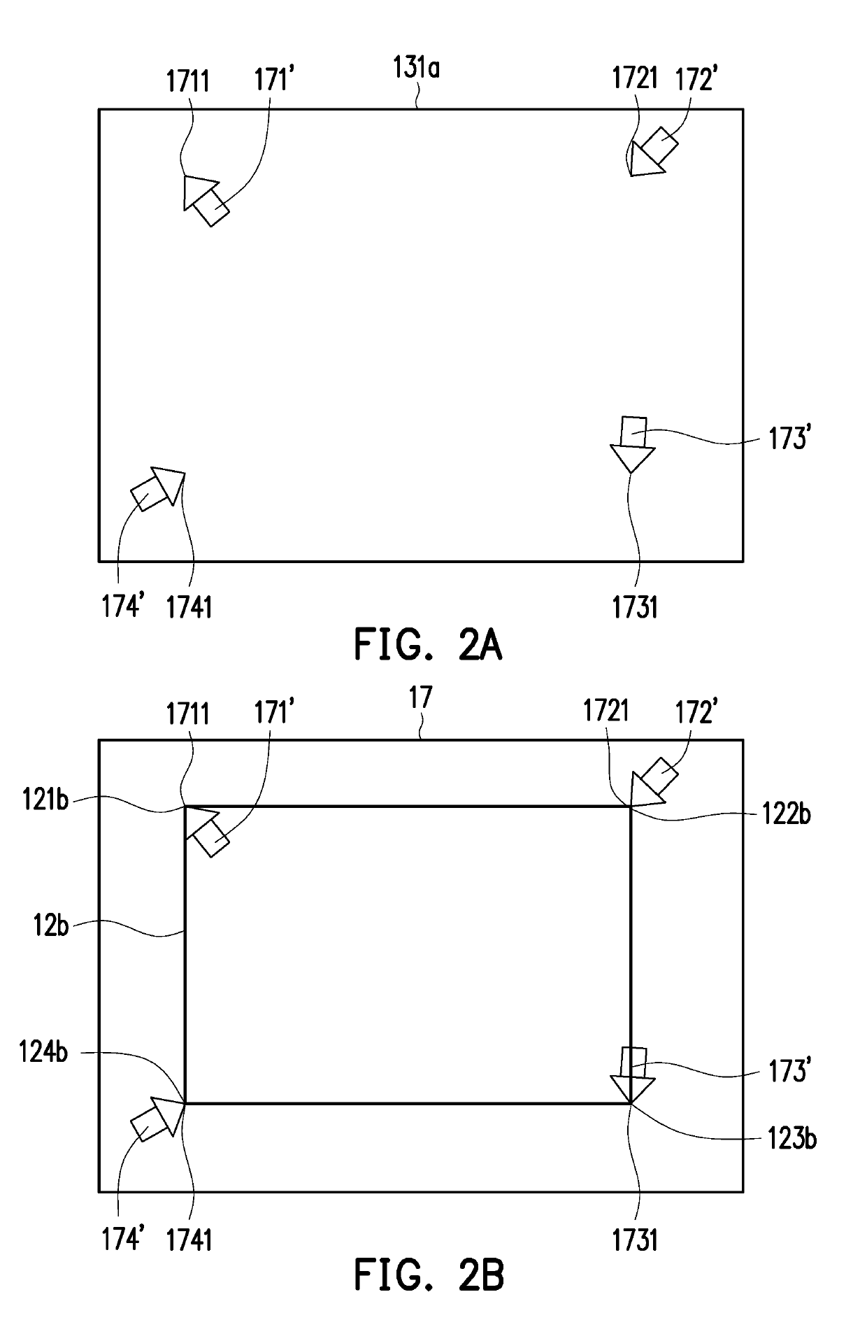
A projection system including an image capturing device, a processing device and a projection device is provided. The image capturing device is used for capturing a first image of a projection surface. The first image includes a plurality of positioning images. The processor receives the first image. The processing device calculates to generate a plurality of positioning points according to the positioning images. The projection device projects a second image to the projection surface according to the positioning points. The second image includes a plurality of deformation points. An amount of the deformation points and an amount of the positioning points on the projection surface are consistent, such that the projected image is automatically adjusted to a range preset by the user.

Description

CROSS-REFERENCE TO RELATED APPLICATION[0001]This application claims the priority benefit of China application serial no. 201711131401.0, filed on Nov. 15, 2017. The entirety of the above-mentioned patent application is hereby incorporated by reference herein and made a part of this specification.BACKGROUND OF THE INVENTIONField of the Invention[0002]The invention relates to a projection system and an image projection method, and particularly relates to a projection system capable of adjusting a projected image according to an image captured by an image capturing device and an image projection method thereof.Description of Related Art[0003]Projection device is a device capable of projecting images to a projection screen for presenting to users. An image correction function of a known projection device is generally too complicated in operation, and the user has to make multiple adjustments to a projected image in order to match the projected image with a predetermined projection regio...

Claims


Application Information

Patent Timeline
Patent Type & Authority Applications(United States)
IPC IPC(8): H04N9/31G06T7/73
CPCH04N9/3185G06T7/74G06T2207/30208H04N9/3194
Inventor PENG, CHIEN-CHUNLIN, CHI-WEILIU, YUNG-CHIAO
Owner CORETRONIC
Learn More