Sealing structure

a technology of sealing structure and sealing plate, which is applied in the direction of shock absorbers, mechanical devices, piston rings, etc., can solve the problems of taking a lot of time and effort to manufacture and handle components, and achieve the effect of improving sliding stability and reducing the number of components

Active Publication Date: 2019-05-23
EAGLE INDS
View PDF5 Cites 6 Cited by
  • Summary
  • Abstract
  • Description
  • Claims
  • Application Information

AI Technical Summary

Benefits of technology

[0011]As described above, the present invention can reduce the number of components and can improve the stability in sliding of a seal portion or a backup ring portion in comparison with conventional techniques.

Problems solved by technology

a) Since the sealing structure 101 has a large number of components, it takes much time and effort to manufacture and handle the components.

Method used


Image

  • Sealing structure
  • Sealing structure
  • Sealing structure

Examples


first embodiment

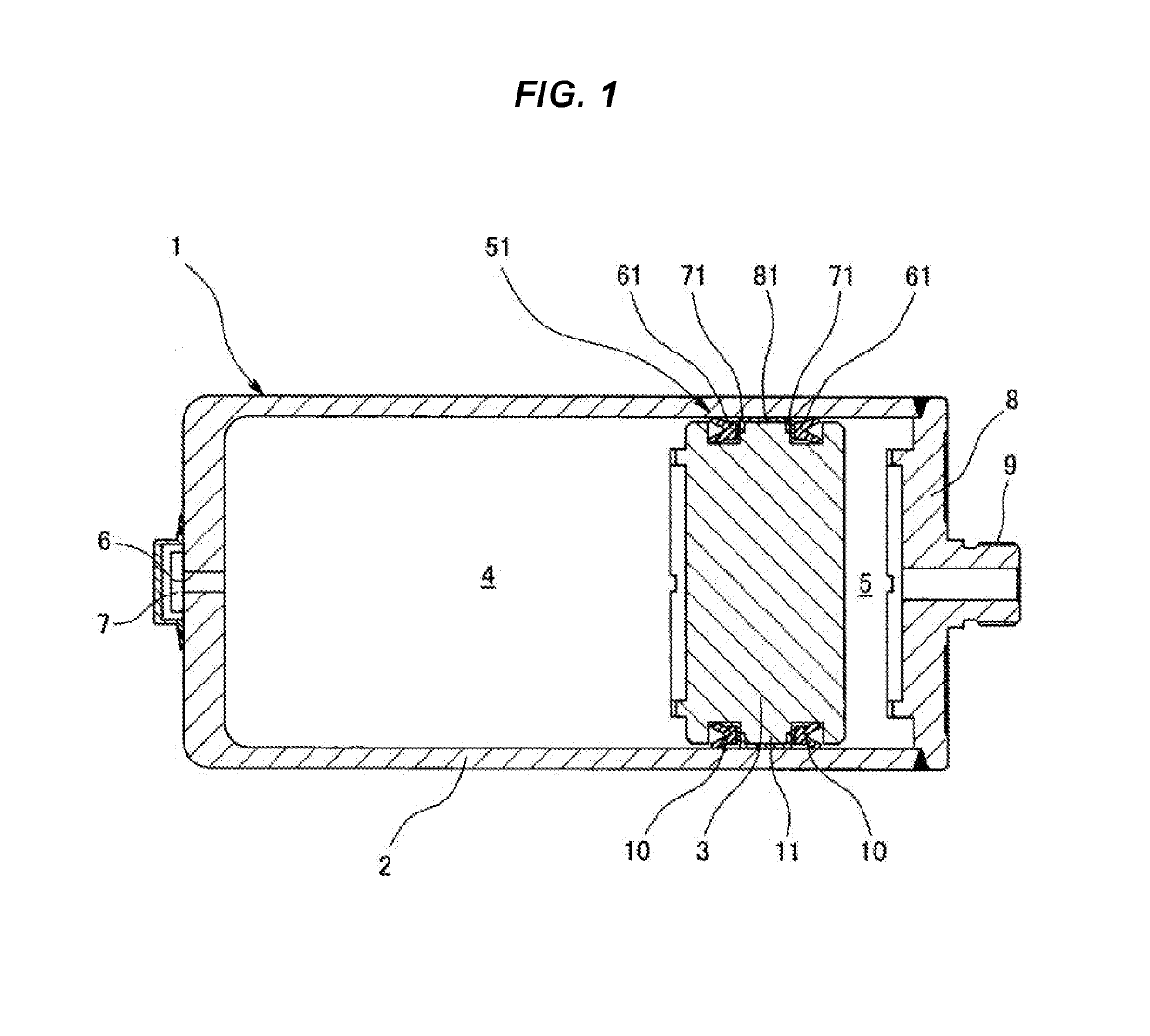
[0022]FIG. 1 illustrates a piston type accumulator 1 having a sealing structure 51 according to a first embodiment of the present invention, in which the internal space of a shell 2 is divided into a gas chamber 4 sealing gas (gas, such as nitrogen gas) and a fluid chamber (liquid chamber) 5 introducing a fluid (liquid, such as pressure oil) by the slidable insertion of a piston 3 into the shell 2 as an accumulator housing. In a bottom surface portion of the shell 2 having a bottomed cylindrical shape, a gas injection hole 6 is provided and is hermetically sealed by a plug 7, an oil port 8 is fixed to an opening portion of the shell 2, and a connection portion 9 to pressure piping is provided thereto.

[0023]Between the shell 2 and the piston 3, the sealing structure 51 according to this embodiment is provided.

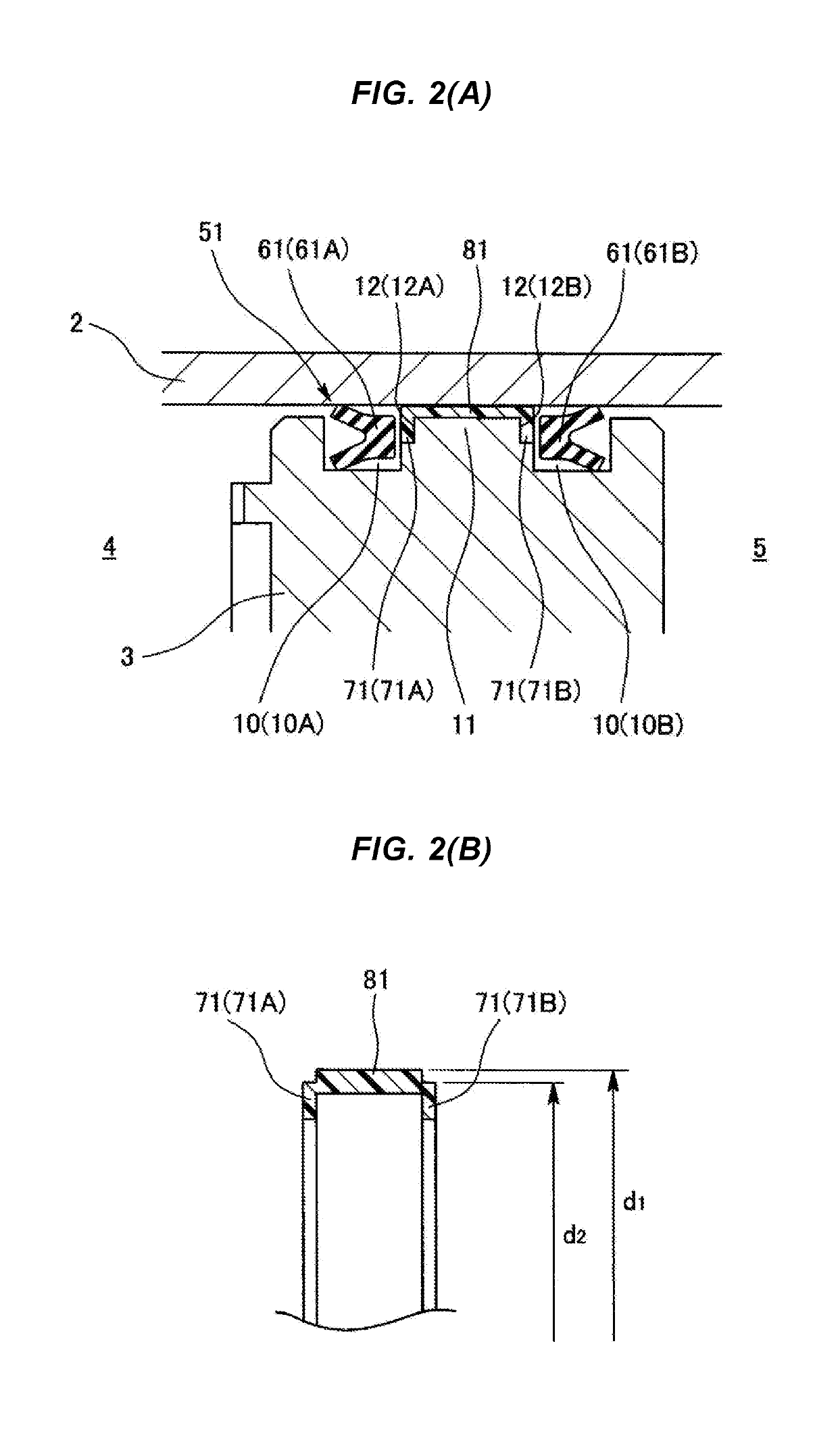
[0024]As illustrated in FIG. 2(A) in an enlarged manner, the sealing structure 51 has seal portions 61 sealing a seal fluid, such as seal gas or a fluid, backup ring portions 71...

second embodiment

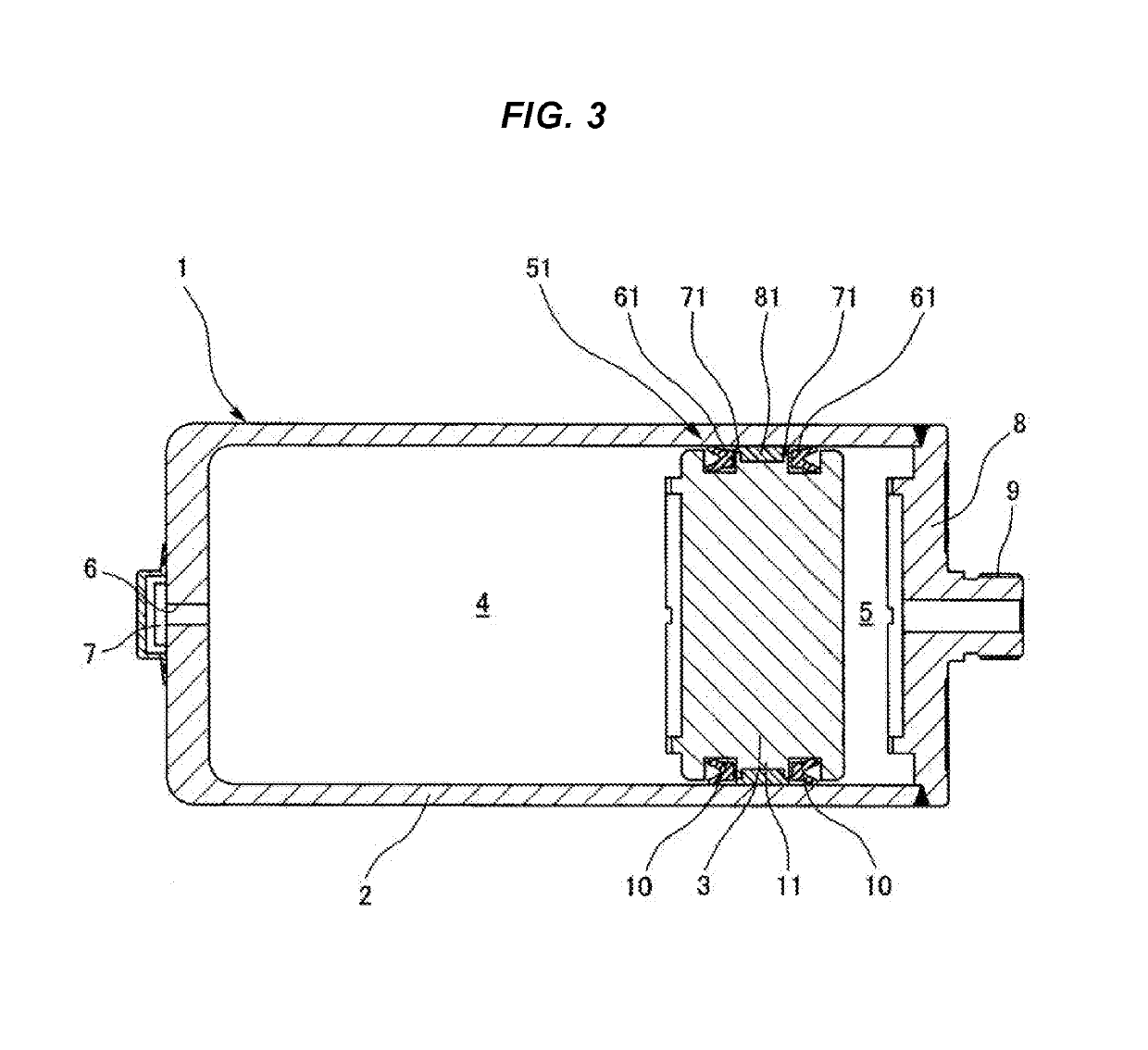
[0031]FIG. 3 illustrates a piston type accumulator 1 having a sealing structure 51 according to a second embodiment of the present invention, in which the internal space of a shell 2 is divided into a gas chamber 4 sealing gas and a fluid chamber 5 introducing a fluid by the slidable insertion of a piston 3 into the shell 2 as an accumulator housing. In a bottom surface portion of the shell 2 having a bottomed cylindrical shape, a gas injection hole 6 is provided and is hermetically sealed by a plug 7, an oil port 8 is fixed to an opening portion of the shell 2, and a connection portion 9 to pressure piping is provided thereto.

[0032]Between the shell 2 and the piston 3, the sealing structure 51 according to this embodiment is provided.

[0033]As illustrated in FIG. 4(A) in an enlarged manner, the sealing structure 51 has seal portions 61 sealing a seal fluid, such as seal gas or a fluid, backup ring portions 71 disposed on the rear surface sides of the seal portions 61 to back up the ...

third embodiment

[0040]FIG. 5 illustrates a hydraulic cylinder 21 having a sealing structure 51 according to a third embodiment of the present invention, in which the internal space of a cylinder tube 22 is divided into a first pressure chamber 25 continuous to a first port 24 and a second pressure chamber 27 continuous to a second port 26 by the slidable insertion of a piston 23 into the cylinder tube 22. In a bottom surface portion of the cylinder tube 22 having a bottomed cylindrical shape, a shaft hole 28 is provided and a cylinder rod 29 is slidably inserted into and passed through the shaft hole 28. A cylinder cover 30 is fixed to an opening portion of the cylinder tube 22 and the second port 26 is provided thereto.

[0041]The sealing structure 51 according to this embodiment is provided between the cylinder tube 22 and the piston 23 (C portion of FIG. 5).

[0042]As illustrated in FIG. 6(A) in an enlarged manner, the sealing structure 51 has seal portions 61 sealing a seal fluid, such as pressure ...


PUM


Abstract

A seal structure is provided which enables a reduction in the number of components and an improvement of the stability in sliding of the seal portion or the backup ring portion. A sealing structure seals two members which move relative to each other, in which a seal portion or a backup ring portion placed between the two members and a bearing portion similarly placed between the two members are formed into an integral structure. The seal portion or the backup ring portion is integrally provided to one end portion in the axial direction or both end portions in the axial direction of the bearing portion having a cylindrical shape. The seal structure is used as a piston seal or a rod seal in hydraulic and pneumatic devices in which a piston is inserted into a shell or a cylinder tube.

Description

CROSS-REFERENCE TO RELATED APPLICATIONS[0001]This application is a U.S. National Stage Application of International Application No. PCT / JP2017 / 017520, filed on May 9, 2017, and published in Japanese as WO 2017 / 195770 A1 on Nov. 16, 2017 and claims priority to Japanese Application No. 2016-097149, filed on May 13, 2016. The entire disclosures of the above applications are incorporated herein by reference.TECHNICAL FIELD[0002]The present invention relates to a sealing structure sealing a seal fluid or the like. The sealing structure of the present invention is used in the automobile-related field or used in the industrial machine field and the like, for example. The sealing structure of the present invention is used as a sealing structure of hydraulic and pneumatic devices, such as an accumulator and a hydraulic cylinder, for example.RELATED ART[0003]Heretofore, a sealing structure 101 illustrated in FIG. 8 is known as a sealing structure for use in a piston type accumulator 1 which i...

Claims


Application Information

Patent Timeline
Patent Type & Authority Applications(United States)
IPC IPC(8): F16J9/12F15B15/14F15B1/24F16F9/36
CPCF16J9/12F15B15/1461F15B15/1452F15B1/24F16F9/368F16F9/36F15B2201/312F16C33/74F15B15/14F16J15/18F16F9/363F16F2230/30
Inventor ARIKAWA, TATSUHIRO
Owner EAGLE INDS
Why Eureka
Try Eureka