Thermostat system

a technology of thermostats and sensors, applied in the field of thermostat systems, can solve the problems of relatively high system cost, inability to integrate the control of existing appliances, and inability of consumers to buy relatively expensive infrastructure, etc., and achieve the effects of no additional cost, modest marginal cost, and little additional cos

Inactive Publication Date: 2019-05-30
DUSHANE STEVEN
View PDF11 Cites 0 Cited by
  • Summary
  • Abstract
  • Description
  • Claims
  • Application Information

AI Technical Summary

Benefits of technology

[0015]These various methodologies allows the system to assess potentially dangerous situations and present a warning message on the same touchscreen face used to program the thermostat. The connection of the doorbell to the thermostat via the Wi-Fi router also enables the occupant of the dwelling to see the person at the door.
[0016]Yet another advantageous aspect of the invention is the fact that thermostats require a significant amount of computing power. By providing the thermostat with a means for Wi-Fi communication and programmability, the same computing power may be used for control of extraneous appliances in any category. Thus, the consumer, at virtually no additional cost, or very little additional cost, can acquire a device for controlling temperature while creating the option for receiving programming allowing remote, programmed, or other control of a wide variety of devices, such as lighting, audio and other equipment with very modest marginal costs.

Problems solved by technology

However, such systems are relatively expensive and generally require the consumer to buy relatively expensive infrastructure in terms of control systems to integrate various appliances together.
Moreover, integration of control of existing appliances is not often practical because most appliances sold today and those which are already in use were designed as self-contained devices.
Moreover, while the idea of a smart home with appliances responsive to the central control system is attractive, as a practical matter the concept is lacking for numerous reasons and this explains why, despite the availability of the technology at very competitive prices, no widespread adoption of such systems has occurred.

Method used


Image

  • Thermostat system
  • Thermostat system
  • Thermostat system

Examples


Embodiment Construction

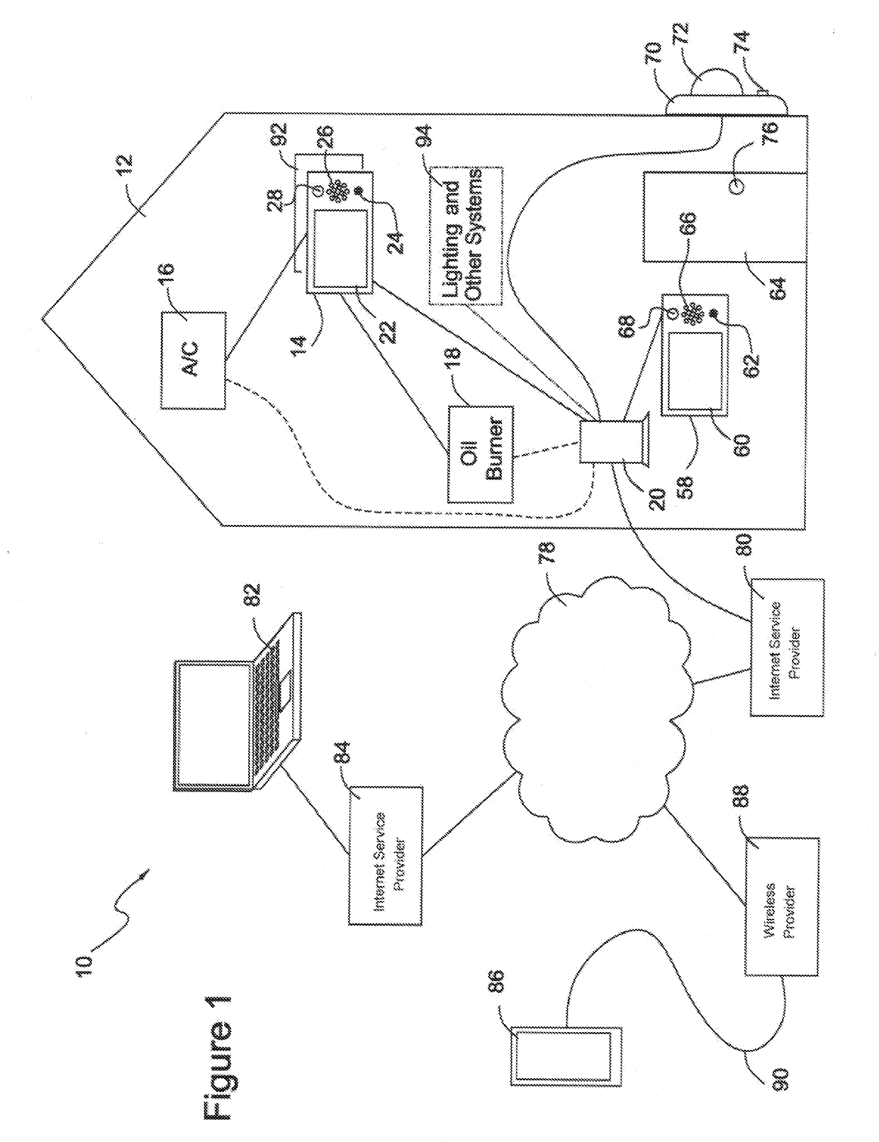
[0025]In accordance with the present invention, locally and remotely reported recognition functions keyed to environmental control objectives are integrated into a priority and security functionality.

[0026]More particularly, with reference to FIG. 1, in accordance with the invention, a system 10 is illustrated which provides to a building 12, such as a home or commercial facility, enhanced HVAC functions keyed to recognition, wherein the condition information is also utilized to enhance system security.

[0027]More particularly, a smart thermostat 14 is located in house 12 and controls, among other things, the operation of air-conditioning equipment 16 and oil burner 18. Air-conditioning equipment 16 and oil burner 18 may be hardwired to smart thermostat 14. Alternatively, air-conditioning equipment 16 and oil burner 18 may be connected to smart thermostat 14 via a router 20. Thermostat 14 may include conventional smart thermostat functions, such as programmability featuring multiple ...


PUM


Abstract

A thermostat system comprises a thermostat located on the inside of the building, comprising (i) a screen display, (ii) a control input for receiving thermostat programming information, and (iii) interface circuitry for coupling to an environmental system comprising one or more items of equipment selected from the group heating, ventilation, and air conditioning equipment. A doorbell is located on the outside of said building. Optionally a camera may be located proximate said doorbell.

Description

TECHNICAL FIELD[0001]In accordance with the present invention, locally and remotely communicated recognition functions keyed to environmental control objectives are integrated into a programming priority and security functionality in an HVAC control system.CROSS REFERENCE TO RELATED APPLICATIONS[0002](Not applicable)STATEMENT REGARDING FEDERALLY SPONSORED RESEARCH OR DEVELOPMENT[0003](Not applicable)BACKGROUND OF THE INVENTION[0004]Today, numerous so-called smart home systems are used to control various appliances in the home, such as environmental systems, coffee makers, lighting, music and so forth. However, such systems are relatively expensive and generally require the consumer to buy relatively expensive infrastructure in terms of control systems to integrate various appliances together. Moreover, integration of control of existing appliances is not often practical because most appliances sold today and those which are already in use were designed as self-contained devices.[000...

Claims


Application Information

Patent Timeline
Patent Type & Authority Applications(United States)
IPC IPC(8): G05D23/24G05D23/30G05D23/19
CPCG05D23/24G05D23/30G05D23/1904F24F11/52F24F11/58F24F11/61F24F11/523F24F11/526G05B19/042G05B15/02G05B2219/2614G05B2219/25168G05B2219/2642F24F11/00G05B15/00G05D23/00
Inventor DUSHANE, STEVEN
Owner DUSHANE STEVEN
Why Eureka
Try Eureka