

High efficiency redundant array of independent memory
a memory and independent technology, applied in the field of computer memory technology, can solve the problems of inherent memory failure, and achieve the effects of reducing the number of ecc memory devices
- Summary
- Abstract
- Description
- Claims
- Application Information
AI Technical Summary
Problems solved by technology
Method used
Image

Examples
embodiment 201
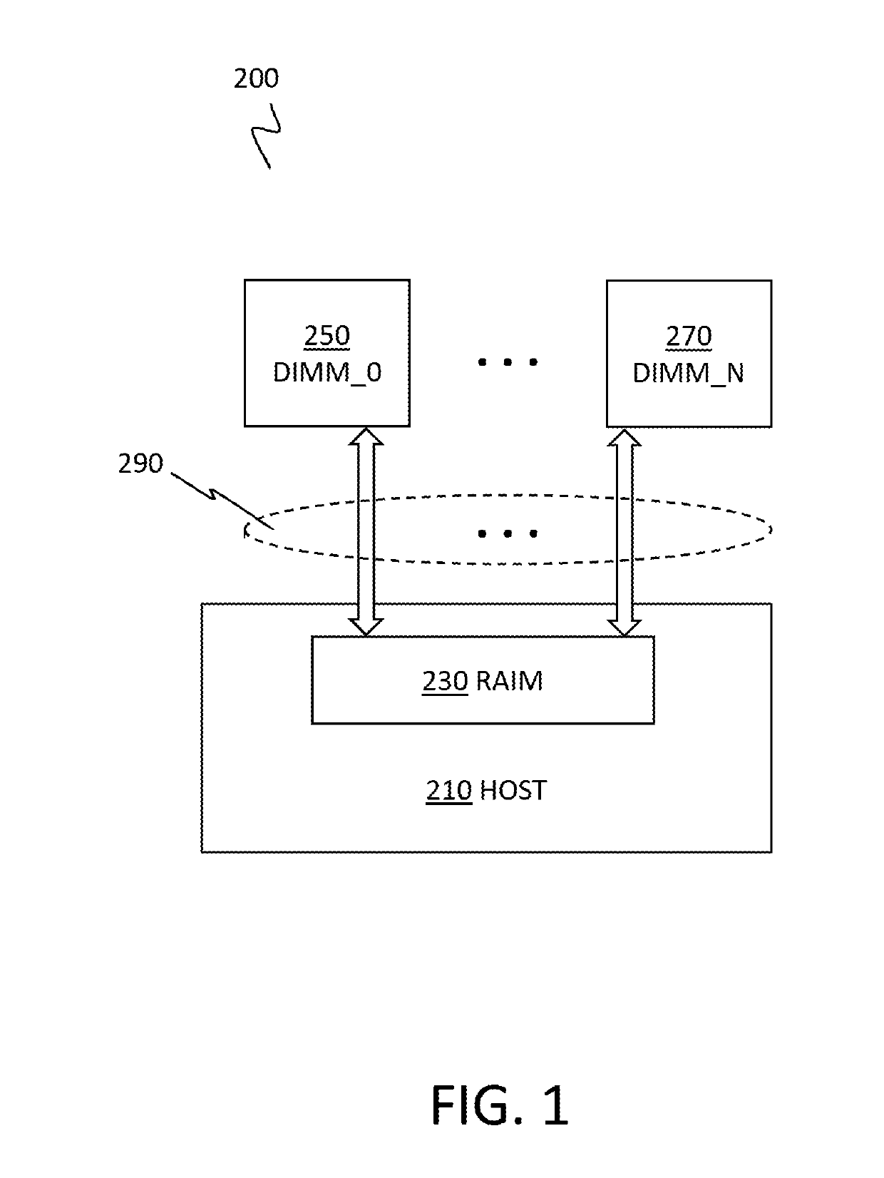
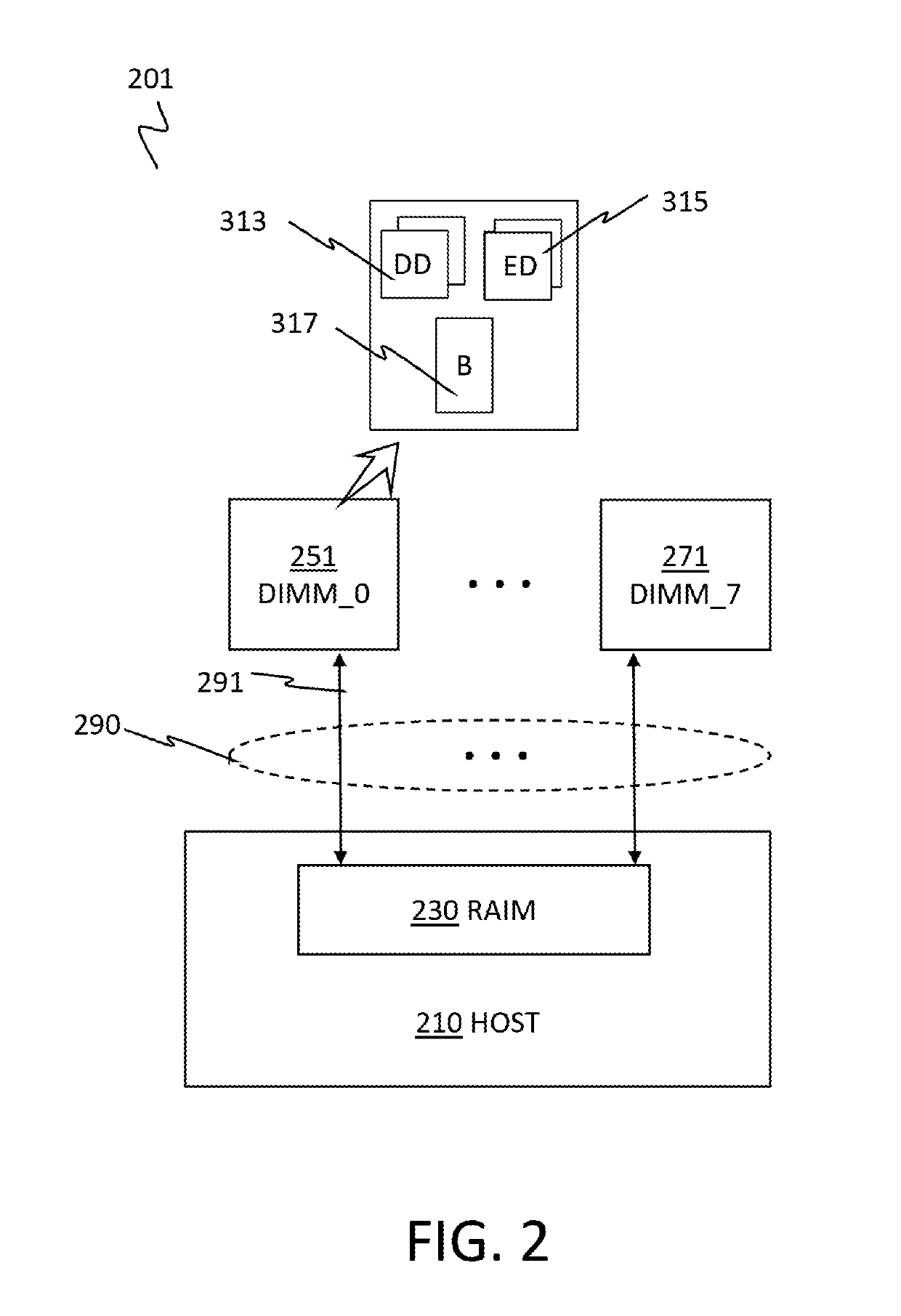
[0042]FIG. 2 depicts an example of an 8-channel, 8-DIMM embodiment 201 of the RAIM memory system 200 of FIG. 1, in accordance with one or more embodiments set forth herein.
[0043]The 8-channel, 8-DIMM embodiment 201 of the RAIM memory system 200 includes eight (8) DIMMs, from DIMM_0251 through DIMM N 271, where N=7. Each DIMM of DIMM_0251 through DIMM_7271, in one example, has the same components. DIMM_0251 has a set of DRAM chips including data DRAMs (DD) 313 and ECC DRAMs (ED) 315, with a ratio of 4:1 data DRAMs to ECC DRAMs.
[0044]Unlike in existing RAIM designs, the 8-channel, 8-DIMM embodiment 201 of the present invention does not require a dedicated DIMM for ECC because the RAIM memory system 200 generates enough ECC symbols to support the aforementioned RAIM functionalities by increasing a number of channels, instead of utilizing a dedicated DIMM for ECC.
[0045]In one embodiment, each DIMM of DIMM_0251 through DIMM_7271 is a ×8 DIMM, and a set of five (5) DRAMs: four (4) data DR...
embodiment 202
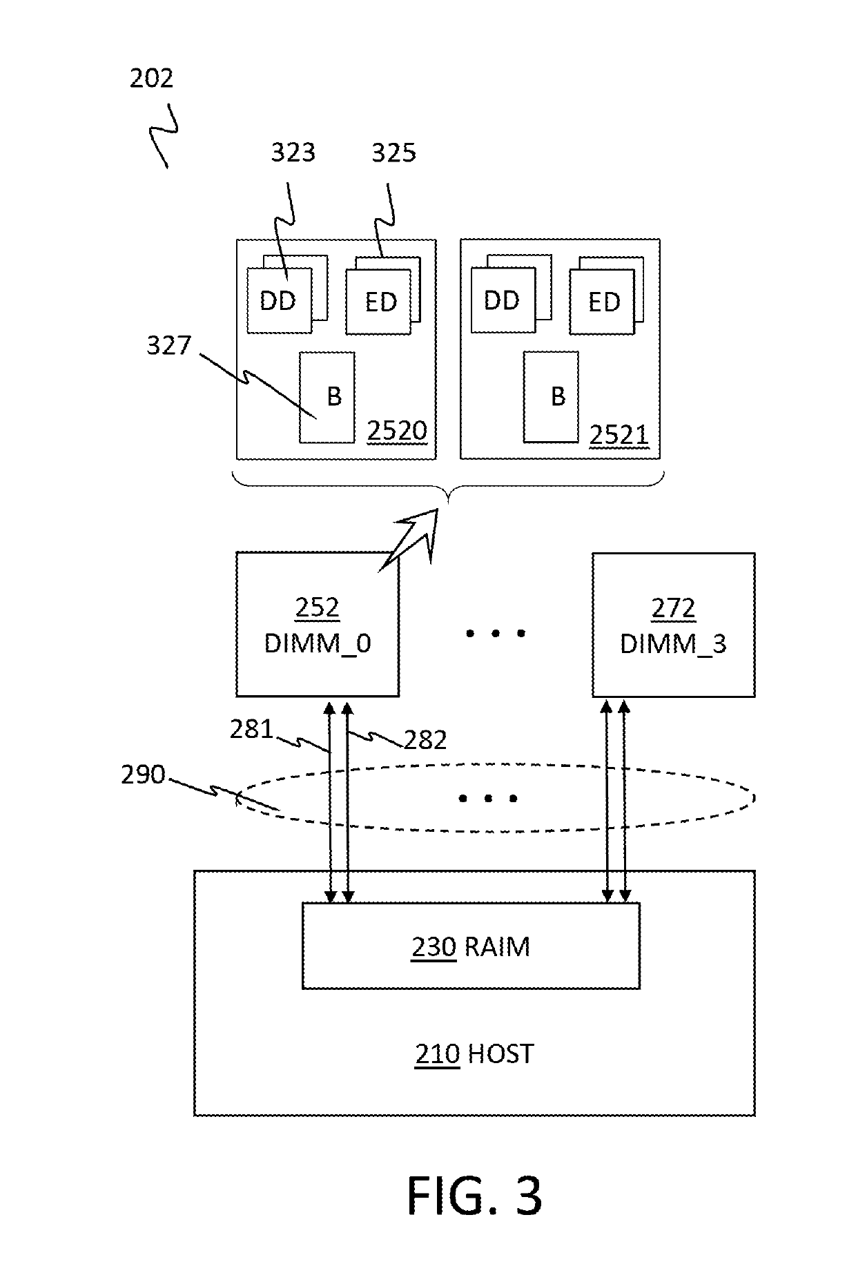
[0047]FIG. 3 depicts an example of an 8-channel, 4-DIMM embodiment 202 of the RAIM memory system 200 of FIG. 1, in accordance with one or more embodiments set forth herein.
[0048]The 8-channel, 4-DIMM embodiment 202 of the RAIM memory system 200 includes four (4) DIMMs, from DIMM_0252 through DIMM N 272, where N=3. In the same embodiment, each DIMM of four compatible DIMMs, DIMM_0252 through DIMM_3272, respectively has two sets of a preconfigured number of DRAM chips, communicating with the RAIM 230, via a channel per set. Accordingly, each DIMM of DIMM_0252 through DIMM_3272 is coupled to the RAIM 230 via the respective two channels. For example, DIMM_0252 is coupled to the RAIM 230 via two channels 281, 282. A first unit 2520 of DIMM_0252 has a set of ten (10) ×4 DRAM chips including eight (8) data DRAMs (DD) 323 and two (2) ECC DRAMs (ED) 325, for a ratio of 4:1 between the numbers of data DRAMs (DD) 323 and ECC DRAMs (ED) 325, and zero or more buffer chips (B) 327, according to t...
embodiment 203
[0050]FIG. 4 depicts an example of an 8-channel, 2-DIMM embodiment 203 of the RAIM memory system 200 of FIG. 1, in accordance with one or more embodiments set forth herein.
[0051]The 8-channel, 2-DIMM embodiment 203 of the RAIM memory system 200 includes, for instance, two (2) DIMMs, from DIMM_0253 through DIMM N 273, where N=1. In one embodiment, the DIMMs are ×4 DIMMs, both DIMM_0253 and DIMM_1273 have four (4) sets of ten (10, or 8+2) DRAM chips communicating with the RAIM 230, via a channel per set. Accordingly, each DIMM of DIMM_0253 through DIMM_1273 is coupled to the RAIM 230 via four channels, 261, 262, 263, 264, as shown in the 8-channel memory interfaces 290. A first unit 2530 of DIMM_0253 has, for example, a set of ten (10) ×4 DRAM chips including eight (8) data DRAMs (DD) 333 and two (2) ECC DRAMs (ED) 335, for a ratio of 4:1 between the number of data DRAMs and the number of ECC DRAMs, and zero or more buffer chips (B) 337, according to the buffer organization. The first...
PUM
 Abstract
Description
Claims
Application Information