

Vascular channel manufacture by deflagration
- Summary
- Abstract
- Description
- Claims
- Application Information
AI Technical Summary
Benefits of technology
Problems solved by technology
Method used
Image

Examples
Embodiment Construction
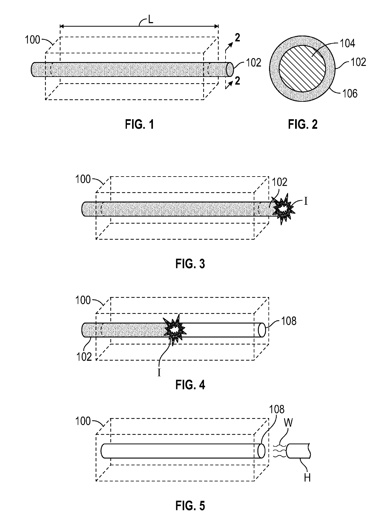
[0025]With reference to FIG. 1, the present disclosure describes a method of forming channels within a substrate 100 using deflagration of a sacrificial material. The substrate 100 may be wholly or partly made of a polymer or a polymer composite. In this method, a sacrificial component 102 is molded directly into the substrate 100 as shown in FIG. 1. For example, the sacrificial component 102 is molded directly to the substrate 100 such that the sacrificial component 102 is at least partially disposed inside the substrate 100. For instance, after molding, a majority of the sacrificial component 102 may be entirely disposed inside the substrate 100 to facilitate the formation of thru-holes. However, at least part of the sacrificial component 102 should be disposed outside of the substrate 100 to allow it to be ignited as discussed below.
[0026]With specific reference to FIG. 2, the sacrificial component 102 includes a combustible core 104 and a protective shell 106 surrounding the com...
PUM
| Property | Measurement | Unit |
|---|---|---|
| Temperature | aaaaa | aaaaa |
| Moldable | aaaaa | aaaaa |
| Metallic bond | aaaaa | aaaaa |
Abstract
Description
Claims
Application Information