
Propel/repel dispenser

a dispenser and screw technology, applied in the direction of transportation and packaging, packaging foodstuffs, packaged goods types, etc., can solve the problems of screw breakage, achieve the effect of eliminating screw breakage, improving threading, and simple structur

Active Publication Date: 2019-06-06
FEDERAL PACKAGE NETWORK
View PDF2 Cites 0 Cited by
  • Summary
  • Abstract
  • Description
  • Claims
  • Application Information

AI Technical Summary

Benefits of technology

[0007]The invention is directed to a screw-operated dispenser that has a thread structure which prevents or eliminates breakage of the screw in the event a user rotates the dispenser's screw in a repel direction when the elevator is in the lowermost repel position.
[0008]The invention comprises an improved threaded screw which is simple in structure and does not require costly additional parts or manufacturing and assembly steps to achieve the desired elimination of breakage of the screw.
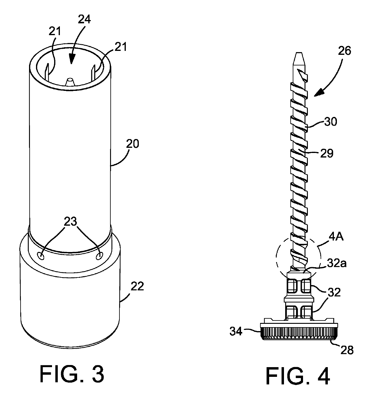
[0009]Accordingly, a propel / repel dispenser is provided having an improved threading on the shaft of the screw. The screw thread in at least the lowermost about 1 to about 1.75 revolutions, preferably about 1.5 revolutions, of the screw thread adjacent the shoulder of a hub in the screw is chamfered so as to provide in the thread surface a bottom edge which is inclined or slanted and not at a right angle to a side wall of the thread. In the event a user causes the turn member to rotate in a repel direction when the elevator is movably engaged with the thread in a lowermost position on the screw shaft, the chamfered edge in at least the lowermost revolutions of the thread of the screw will cause the engaged elevator thread to override by sliding over or around the screw thread, thereby preventing breakage of the screw shaft and maintaining the operability of the dispenser.
[0010]The improved screw of the invention works particulary well when the hub of the screw is increased in length. This provides for additional spacing at the base of the screw shaft between the elevator and the bottom wall of the tubular body. This structure prevents the elevator from engaging the bottom wall of the tubular body and subjecting it to unwanted downward pressure which may cause the screw to break in the event the user turns the screw in the wrong direction. The lengthened hub may be provided by having two or more stacked hubs or by increasing the length of a single hub. The stacked hubs may provide for a sturdier screw and dispenser.
[0011]In use of the propel / repel dispenser of the invention, the product is stored within the tubular body. The product is supported in the body by the elevator as a support which travels inside the body along the body's length. The elevator is received on a threaded shaft of a dispensing screw of the invention. The shaft of the dispensing screw is inside the tubular body. At the end of the screw is a turn member. The turn member is fitted into a base which in conjunction with the screw is connected to the tubular body. The base has a mating configuration to maintain the turn member in place in the base and to cause the turn member to rotate in response to rotation of the base by a user.
[0013]The screw-operated dispenser of the invention is configured such that the turn member when caused to be rotated in one direction propels the elevator and product supported thereon upward and out of the container through the top opening in the tubular body, and when turned in a second and opposite direction repels the elevator downward to a lowermost position on the threaded shaft. If a user mistakenly rotates the turn member in a repel direction when the elevator is in a lowermost position, the lower chamfered revolutions of the screw thread allow the thread of the elevator to override or to slip past the thread on the screw shaft. Therefore, such incorrect rotation of the turn member will not place stress and / or pressure on the engaged threads of the screw, thereby preventing breakage of the screw shaft and rendering the dispenser inoperable.

Problems solved by technology

This structure prevents the elevator from engaging the bottom wall of the tubular body and subjecting it to unwanted downward pressure which may cause the screw to break in the event the user turns the screw in the wrong direction.

Method used


Image

  • Propel/repel dispenser
  • Propel/repel dispenser
  • Propel/repel dispenser

Examples


Embodiment Construction

[0028]Having described the invention in general terms, a description of presently preferred embodiments is set forth with reference to the drawings.

[0029]Referring to FIG. 3, a perspective view of a propel / repel screw-operated dispenser of the invention is shown. Tubular body 20 is shown in the preferred form of a cylinder. A base 22 is attached in a conventional manner to tubular body 20 to allow rotation of base 22 in relation to body 20. For convenience of discussion, the propel / repel dispenser will be described and shown in terms of a lip balm stick applicator. Necessarily variations in size and shape are possible depending on the use of the product contained in the dispenser. For example, conventional lip balm applicators have a body size of approximately ⅝″ in diameter and 2″ in length. The tubular body is, as well as the other parts of the applicator, preferably manufactured from plastic as conventionally known in the art. Body 20 has an open dispensing end 24. A removable ca...


PUM


Abstract

A screw-operated dispenser providing for prevention of breakage of an engaged screw when a user rotates a turn member in the wrong direction, i.e., repels rather than propels an elevator. A tubular body holds a supply of product, which is dispensed by action of the elevator along a threaded shaft upon turning a base to either propel or repel the elevator along the shaft which is threadably engaged with the elevator. Certain lowermost revolutions of the thread on the shaft are chamfered at the bottom edge thereof so that when the elevator is in a lowermost position on the screw shaft and a user mistakenly rotates the turn member in a repel direction, the thread of the elevator will not engage, i.e., will override, the thread of the screw shaft thereby eliminating stress and / or pressure between the threads which may result in breakage of the screw shaft and render the dispenser inoperable.

Description

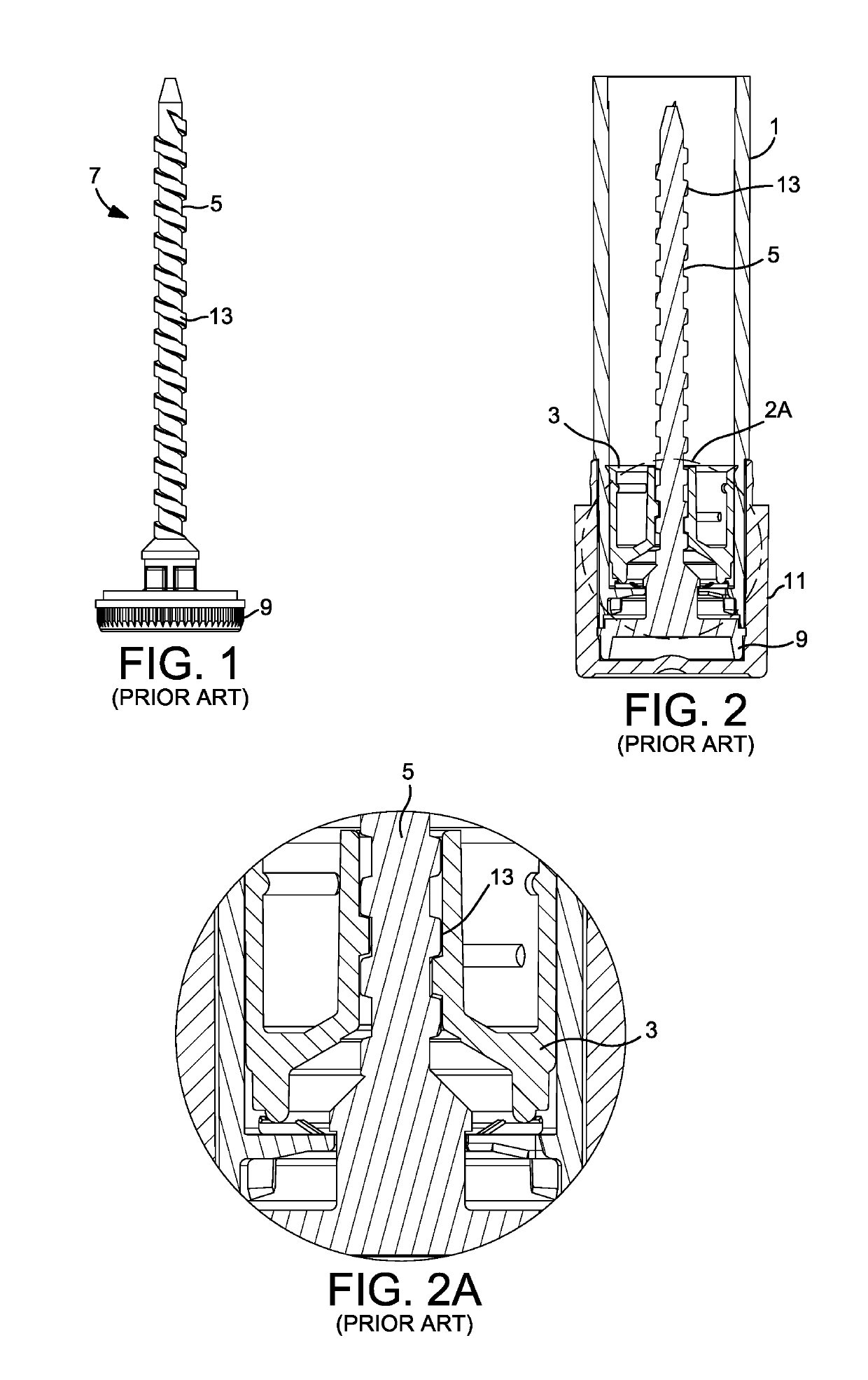
FIELD OF THE INVENTION[0001]The invention relates to a screw-operated propel / repel dispenser for dispensing a highly viscous product, such as a substantially solid or solid product. More particularly, the invention relates to a screw-operated propel / repel dispenser having an improved screw which prevents breakage of the screw when a user operates the dispenser to move the screw in a repel direction when the elevator of the dispenser is in a lowermost repel position, i.e., the user mistakenly turns the screw in the wrong direction placing stress and / or pressure on the screw.BACKGROUND OF THE INVENTION[0002]Screw-operated dispensers are known in the art. They are useful for dispensing products such as lip balms, cosmetics and the like.[0003]In a screw-operated dispenser of the prior art such as shown in FIGS. 1, 2 and 2A, product to be dispensed sits within a tubular body 1 of cylindrical or other shape. The product is supported in the body by an elevator 3 which travels inside the bo...

Claims


Application Information

Patent Timeline
Patent Type & Authority Applications(United States)
IPC IPC(8): B65D83/00B05C17/01
CPCB65D83/0016B05C17/0116B65D83/0011A45D40/04
Inventor DAKOLIOS, STEVEN R.ERICKSON, KENDALL L.
Owner FEDERAL PACKAGE NETWORK
Learn More