
Power supply system

Active Publication Date: 2019-06-06
TOYOTA JIDOSHA KK
View PDF0 Cites 0 Cited by
  • Summary
  • Abstract
  • Description
  • Claims
  • Application Information

AI Technical Summary

Benefits of technology

The patent describes a technology that allows a DC-DC converter to automatically output a fixed voltage and charge a low-voltage battery, even when there is no command from a higher electronic control unit (ECU). This prevents the converter from being operated unnecessarily and consuming excessive electric power. The technology also includes a relay that prevents the contact point from being stuck when the current flowing through the relay is substantially zero. Overall, the technology improves the efficiency and reliability of the overall power system.

Problems solved by technology

As a result, the low-voltage battery eventually runs out, and accordingly, the low-voltage load may not normally operate.

Method used


Image

  • Power supply system
  • Power supply system

Examples


Embodiment Construction

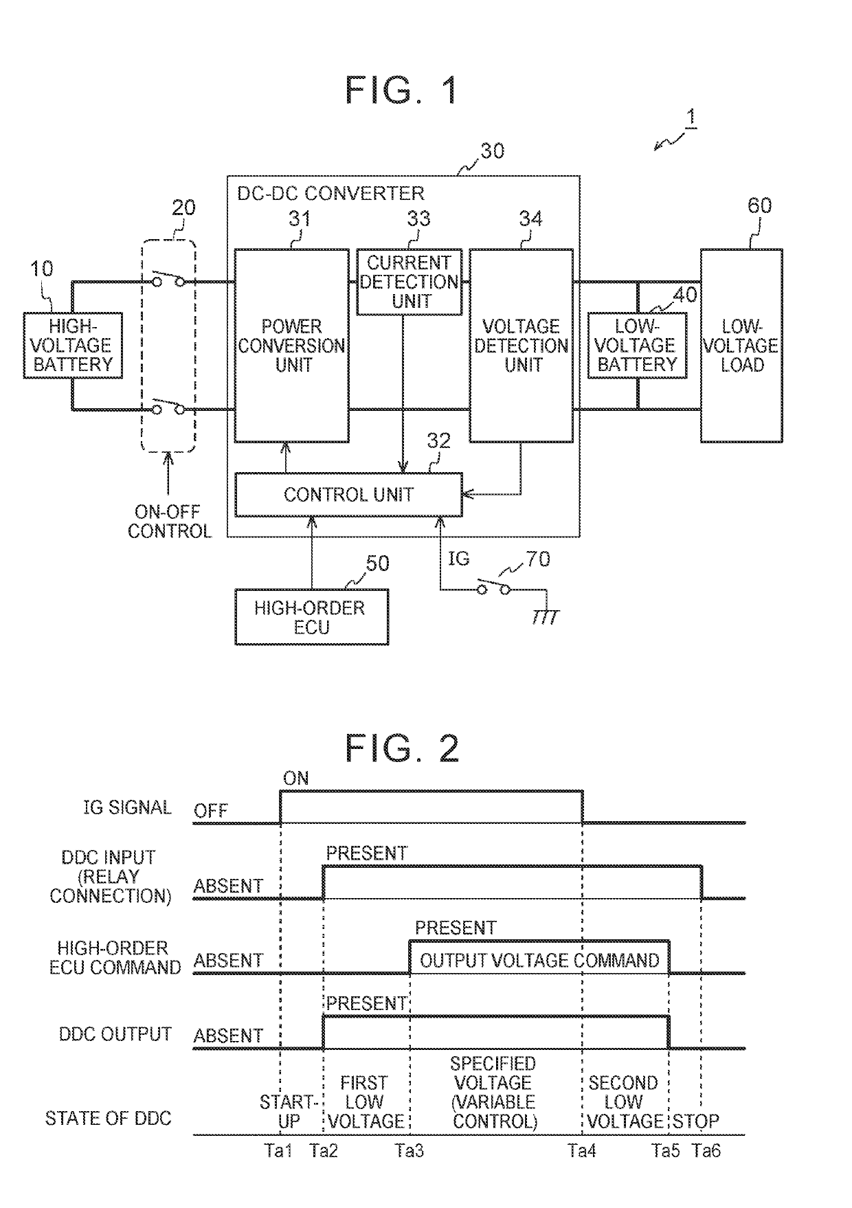
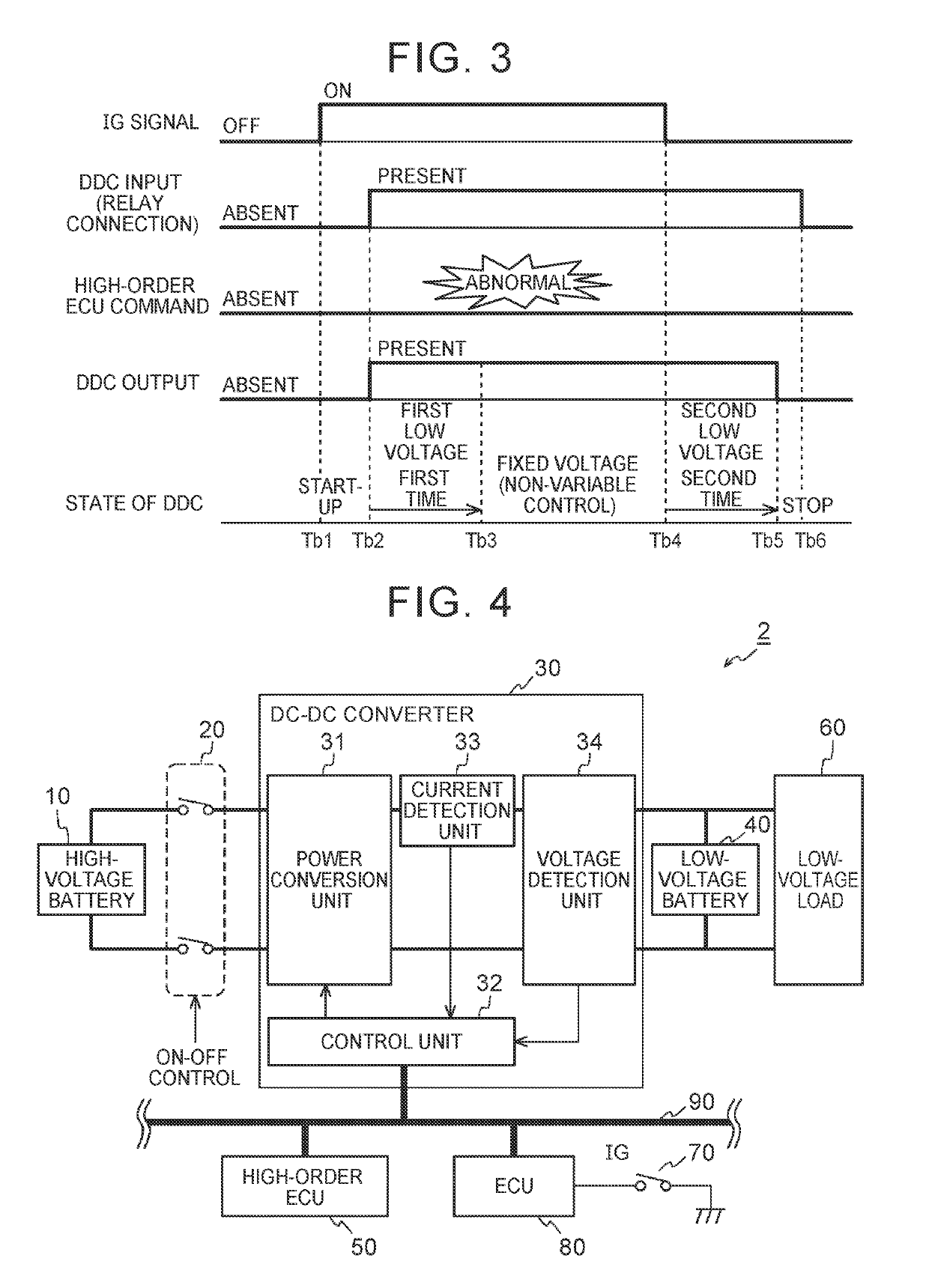
[0022]A power supply system according to an embodiment is configured to supply electric power from a high-voltage battery to a low-voltage battery and a low-voltage load on the basis of a command from a high-order electronic control unit (ECU). In the power supply system, start-up of a direct current-direct current converter (DC-DC converter) is triggered by a state transition of an ignition (IG) signal from an off state to an on state (i.e., from OFF to ON). In other words, DC-DC converter is started up based on the state transition of the IG signal from OFF to ON (i.e., the DC-DC converter is started up when the IG signal changes from OFF to ON). Then, a low voltage is output from the DC-DC converter after the start-up of the DC-DC converter. In the case where an output voltage command is not provided from the high-order ECU by a time at which a specified time elapses after the output of the low voltage is started, a fixed voltage is output from the DC-DC converter. Thus, even whe...


PUM


Abstract

A power supply system includes a DC-DC converter, a relay, and a control unit configured to i) start up the DC-DC converter based on a state transition of an ignition signal from OFF to ON, ii) cause the DC-DC converter to output a first low voltage when a high-voltage battery is connected to the DC-DC converter by the relay, iii) cause the DC-DC converter to output a voltage specified by an output voltage command in a case where the output voltage command is provided from a high-order ECU after output of the first low voltage is started, and iv) cause the DC-DC converter to output a fixed voltage higher than the first low voltage in a case where the output voltage command is not provided from the high-order ECU by a time at which a first time elapses after the output of the first low voltage is started.

Description

INCORPORATION BY REFERENCE[0001]The disclosure of Japanese Patent Application No. 2017-234115 filed on Dec. 6, 2017 including the specification, drawings and abstract is incorporated herein by reference in its entirety.BACKGROUND1. Technical Field[0002]The disclosure relates to a power supply system that is provided in a vehicle.2. Description of Related Art[0003]A power supply system is disclosed in, for example, each of Japanese Patent Application Publication No. 2012-060819 (JP 2012-060819 A) and Japanese Patent Application Publication No. 2012-182894 (2012-182894 A). In the power supply system, a DC-DC converter supplies power from a high-voltage battery to a low-voltage battery and a low-voltage load on the basis of an output voltage command provided by a high-order ECU.SUMMARY[0004]In the power supply system described in each of the above patent documents, in the case where the output voltage command is no longer provided to the DC-DC converter due to failure of the high-order...

Claims


Application Information

Patent Timeline
IPC IPC(8): H02J7/00B60R16/033
CPCH02J7/007H02J7/0068B60R16/033H02J7/0031H02J7/342H02J2310/46Y02T10/70
Inventor TERAO, KENJI
Owner TOYOTA JIDOSHA KK
Learn More