Vertical mill roller

a vertical mill roller and roller technology, applied in the field of vertical mill rollers, can solve the problems of large carbon dioxide discharge of coal and petroleum coke, difficult numerical value of commitment, and inability of resource-poor japan to immediately stop coal among all fossil fuels, so as to prevent extreme wear, improve wear to the same level, and achieve the effect of effective grinding surface area

Active Publication Date: 2016-03-22
ING SHOJI
View PDF11 Cites 0 Cited by
  • Summary
  • Abstract
  • Description
  • Claims
  • Application Information

AI Technical Summary

Benefits of technology

[0041]The vertical mill roller according to the present invention can prevent extreme wear unique to the slit grooves by making the main grinding surface subjected to wear most smooth on the basis of the worldwide new grinding theory, and can at least improve wear to the same level of wear of the smooth surface, and further make the effective grinding surface area 100%, which contribute to improvement of the production volume of the fine powder.
[0042]For power consumption of the grinder, by decreasing the area of the raw material transfer surface through the role sharing of the grinding surface to make the contact area smaller than that of the smooth surface roller, wasted electric power can be reduced.
[0043]For the present inventors who have continued to research the shape of the grinding surface for a long time, one of the final objects is to establish the comprehensive grinding surface technology including the slit grooves and the screw grooves. The present inventors succeeded in developing the perfect shape of the grinding surface that achieved unprecedented excellent effects by further improving, especially, the effects of the screw grooves. The result is the above-mentioned innovative grinding surface shape.

Problems solved by technology

However, coal and petroleum coke have a major disadvantage of discharge of a large amount of carbon dioxide.
This commitment shows an extremely difficult numerical value to achieve, and the public and the Industry must fulfill their large obligations.
Since the use of coal and petroleum coke as fuels for power generation leads to discharge of a large amount of carbon dioxide, these fuels are regarded as sources of the all evil in terms of discharging of carbon dioxide.
However, it is impossible for resource-poor Japan to immediately stop coal among all fossil fuels.
At least until nuclear power generation and clean alternative energy are prepared, the use of coal cannot be stopped because of its economic efficiency, its convenience, rich reserve and difficulty in depletion.
Although the reduction effect achieved by one grinding mill is insignificant, the mills used all over the world is too numerous to count, which result in drastic reduction of the amount of discharged carbon dioxide.
On the contrary, circumferential grooves vertical to the roller shaft (roller circumferential direction) cannot obtain the good biting property of the ground raw material.
However, the long-term experience and experiment study of the present inventors demonstrate that the vertical grinding roller in which the slit grooves are formed on the entire grinding surface to improve the biting property and the grinding roller having the screw grooves that are excellent in the transfer property of the ground raw material have common problems.
That is, both in the roller with the slit grooves and the roller with the screw grooves, their added values cannot be completely exhibited for the ground raw material having a high hardness due to excessive wear, and the inventors have looked for its solution.
As a result, two following problems related to the roller circumferential direction and the roller shaft direction emerged.
The first problem relates to wear of the grinding surface of the grinding roller in the roller circumferential direction (rotating direction).
When a hard material is ground, the slit grooves are disadvantageously prone to early wear.
However, due to the hard material, the sharp gear-like shape extremely wears and early changes to a mountain-like shape, the grinding efficiency gradually lowers.
At the same time, replacement is required within a short time as a result of the extreme wear.
Further, in the case where highly hard silica stone and ceramics, non-weathered blast furnace slag, and low-quality coal containing much ash are ground, the wear speed extremely increases.
The second problem relates to wear of the grinding surface of the grinding roller in the roller shaft direction.
In fact, it turns out that the existing smooth surface roller does not perform the function.
When a hard ground raw material or a moist ground raw material is ground, since the grinding surface is a smooth surface, the biting property and the transfer property are poor, and the roller slips, thereby generating a large oscillation in the grinder itself to make its operation difficult.
As a result, the production volume of fine powder decreases.
When excessive pressure is applied to the roller in order to suppress slip and oscillation of the roller, an axis current of the mill increases, generating a large power loss.

Method used


Image

  • Vertical mill roller
  • Vertical mill roller
  • Vertical mill roller

Examples


example

Experimental Equipment

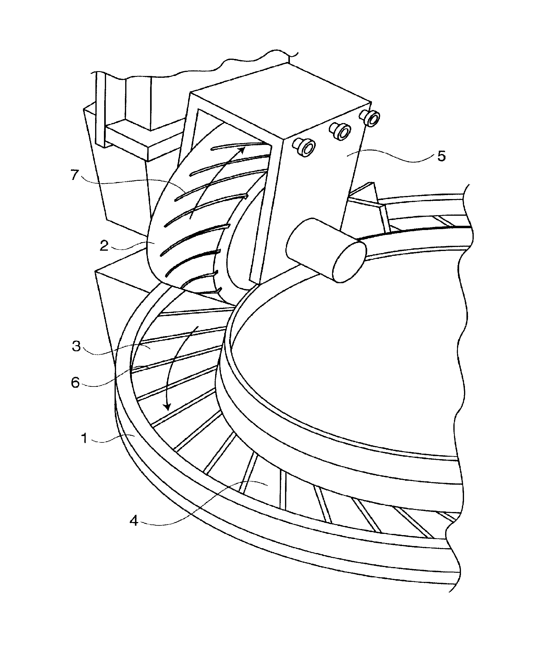
[0065]To estimate the effectiveness of the present invention, a Loesche type-like experimental compact grinder having the trapezoidal roller as a kind of the vertical roller mill was manufactured. As shown in FIG. 6, in this grinder, a grinding roller 2 is opposed to a surface of an outer circumference of a horizontal rotating table 1 as a base member. The grinding roller 2 is a vertical roller shaped like a truncated cone, and is arranged inclined such that the large-diameter side faces the outer circumferential side, the small-diameter side faces the center, and its surface opposed to a table 1 is horizontal. For purpose of a tester, the number of the rollers is one.

[0066]The outer circumferential surface of the grinding roller 2 has a plurality of screw grooves 7. The plurality of screw grooves 7 discharge the ground raw material from the rotational center toward the outer circumference with rotation, and feed the material into a grinding chamber formed of t...


PUM


Abstract

In grinding of a raw material by a vertical roller mill, highly-efficient grinding is performed irrespective of the type of the raw material, and the life of the mill roller is extended. In order to achieve these, in a grinding roller used in a vertical roller mill, an outer circumferential surface of the roller as a grinding surface is divided into a main grinding surface that mainly performs pulverizing and a grinding surface other than the main grinding surface. The main grinding surface is made smooth, and the grinding surface other than the main grinding surface is a raw material transfer surface in which slit grooves inclined at 90 degrees or an angle exceeding 45 degrees relative to a roller circumferential direction or screw grooves inclined at 45 degrees or smaller relative to the roller circumferential direction are formed.

Description

TECHNICAL FIELD[0001]The present invention relates to a vertical mill roller used in a vertical roller mill and, in particular, a universal vertical mill roller suitable for pulverizing coal, petroleum coke, and the like, as well as grinding materials such as limestone, ground fine powder of which tends to adhere to a surface of a roller.BACKGROUND ART[0002]Power generating boilers using coal or petroleum coke as fuel have been heavily used. Reasons for the heavy use are low fuel costs, easy adjustment of electricity generated and so on, and therefore, developing countries such as China as well as Japan depend on coal and petroleum coke for most of electricity generated. However, coal and petroleum coke have a major disadvantage of discharge of a large amount of carbon dioxide.[0003]To the world, Japan made a public commitment to reduce the amount of discharged carbon dioxide in the year 1990 by 25% until the year 2020. This commitment shows an extremely difficult numerical value to...

Claims


Application Information

Patent Timeline
Patent Type & Authority Patents(United States)
IPC IPC(8): B02C15/04B02C15/00
CPCB02C15/004B02C15/00B02C15/007
Inventor KAWATSU, HAJIME
Owner ING SHOJI
Why Eureka
Try Eureka