
Apparatus and method for controlling charge and discharge, and program

a technology of apparatus and discharge, applied in the direction of electric vehicles, transportation and packaging, ac network load balancing, etc., can solve problems such as power system instability, and achieve the effect of reducing wasted electric power

Inactive Publication Date: 2019-03-28
NEC CORP
View PDF1 Cites 0 Cited by
  • Summary
  • Abstract
  • Description
  • Claims
  • Application Information

AI Technical Summary

Benefits of technology

The patent describes a device that can control the charging and discharging of a battery more efficiently, reducing wasted power. This device can optimize the way power is output from the battery, improving its overall performance. The invention has been developed using a method and program that are designed to work with the device. The technical effects of this invention are improved battery performance and reduced power waste during power output control.

Problems solved by technology

As described in Non-Patent Documents 1 and 2, in recent years, a surplus electric power flowing back to a power system has increased due to a rapid increase of distributed type power supply (power generation apparatus) using renewable energy centering on sunlight, and there is a problem that the power system becomes unstable.

Method used


Image

  • Apparatus and method for controlling charge and discharge, and program
  • Apparatus and method for controlling charge and discharge, and program
  • Apparatus and method for controlling charge and discharge, and program

Examples


first example embodiment

[0047]A power storage system, a charging and discharging control apparatus, a method of controlling the apparatus, and a program according to a first example embodiment of the present invention will be described below.

[0048]The charging and discharging control apparatus of the example embodiment controls charging and discharging of a lithium ion secondary battery.

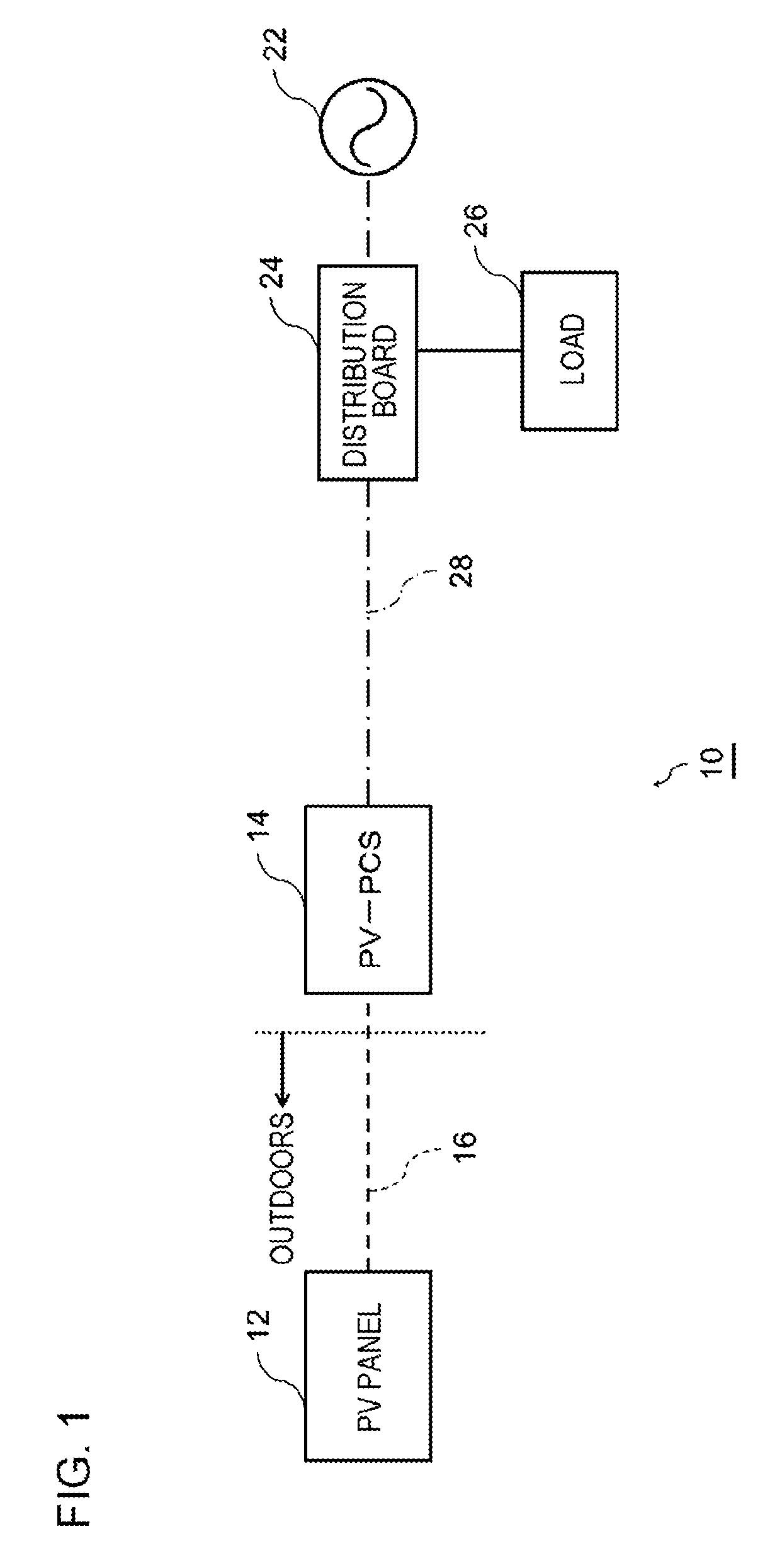
[0049]FIG. 1 is a schematic block diagram illustrating a configuration example of a photovoltaic (PV) system 10.

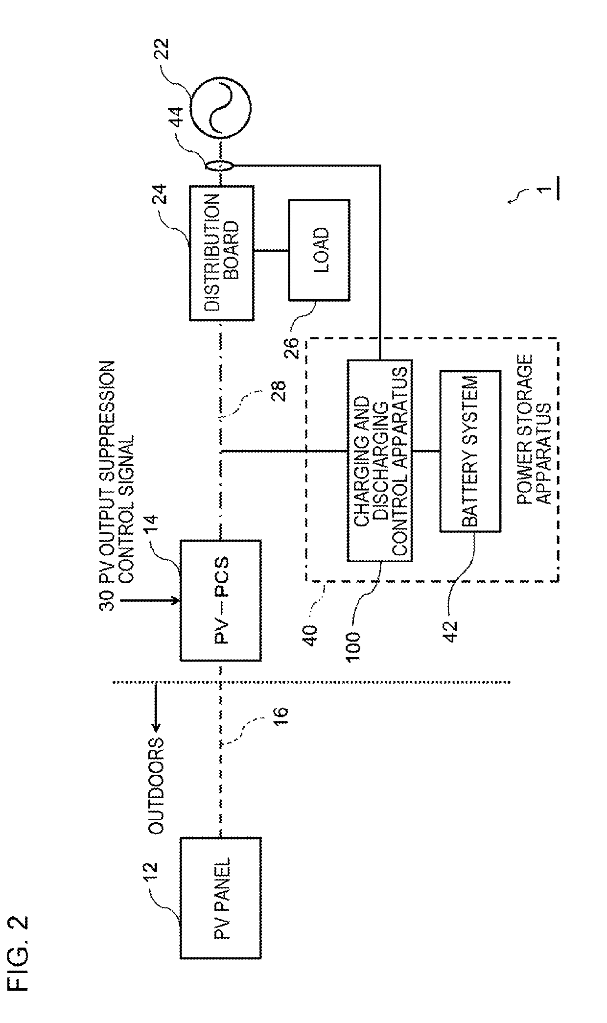
[0050]FIG. 2 is a schematic block diagram illustrating a configuration example of the power storage system 1 according to the example embodiment of the present invention. The power storage system 1 illustrates a configuration after a power storage apparatus 40 is added to an AC power line 28 (28a and 28b) side of the existing PV system 10 in FIG. 1.

[0051]In each drawing of the present specification, configurations of portions that are not related to the spirit of the invention are not described and not illustrated...

second example embodiment

[0141]Next, the power storage system according to a second example embodiment of the present invention will be described below.

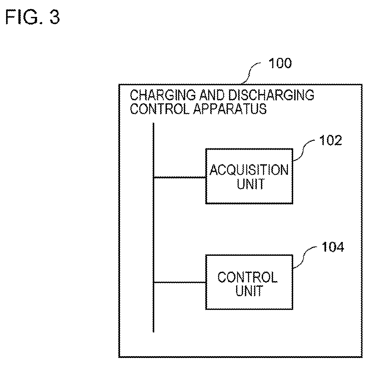
[0142]The power storage system of the example embodiment has the same configuration as that of the power storage system 1 of the aforementioned example embodiment in FIG. 2, and will be described below with reference to FIG. 2 and FIG. 3.

[0143]In the example embodiment, an example of a method of controlling charging and discharging a storage battery in the control unit 104 of the aforementioned example embodiment will be described in detail.

[0144]A specific control method will be described below.

[0145]FIG. 9 is a flowchart illustrating an example of operations of the charging and discharging control apparatus 100 according to the example embodiment.

[0146]Herein, it is considered that the current flowing through the AC power line 28b, acquired by the acquisition unit 102, takes a negative value when the current is flowing in the direction from the distributio...


PUM


Abstract

The charging and discharging control apparatus includes an acquisition unit that acquires at least one of a direction and magnitude of electric power flowing between an AC power line and power system, and a control unit that controls charging of the power storage apparatus based on a change in at least one of the direction and magnitude of electric power flowing between the AC power line and power system when a charging amount to the power storage apparatus is increased by a predetermined amount.

Description

TECHNICAL FIELD[0001]The present invention relates to an apparatus and a method for controlling charge and discharge, and a program.BACKGROUND ART[0002]Patent Document 1 describes an example of a power supply system in which a so-called peak shift operation is performed, that is, charging of the output of a photovoltaic power generation apparatus is performed in a power storage apparatus during a daytime zone and discharging is performed during a nighttime zone so that electric power is supplied to a load apparatus. In the system described in Patent Document 1, a charging and discharging amount of the power storage apparatus is predicted from the demand prediction data of the load apparatus and power generation output prediction data predicted using weather forecast data, and based on the predicted values, stable power supply to the load apparatus is implemented by controlling a power generation amount of the power generation apparatus or by suppressing the electric power consumptio...

Claims


Application Information

Patent Timeline
IPC IPC(8): H02J7/00H02J7/02H02J7/35H02J7/34H02J3/32
CPCH02J7/0068H02J7/02H02J7/35H02J7/34H02J3/32
Inventor HASEGAWA, HIDEYUKI
Owner NEC CORP
Learn More