Power management server, power management method, and power management system

a technology of power management server and power management method, which is applied in the direction of information technology support system, systems intergating technology, instruments, etc., can solve the problem that the power flow amount or the reverse power flow amount cannot be appropriately controlled by only the information measured by the smart meter

Active Publication Date: 2019-06-13
KYOCERA CORP
View PDF0 Cites 3 Cited by
  • Summary
  • Abstract
  • Description
  • Claims
  • Application Information

AI Technical Summary

Problems solved by technology

However, when the facility is provided with a distributed power supply that allows a reverse power flow from the facility to the power grid, there is a possibility that the power flow amount or the reverse power flow amount cannot be appropriately controlled by only the information measured by the smart meter.

Method used


Image

  • Power management server, power management method, and power management system
  • Power management server, power management method, and power management system
  • Power management server, power management method, and power management system

Examples


embodiment

[0018](Power Management System)

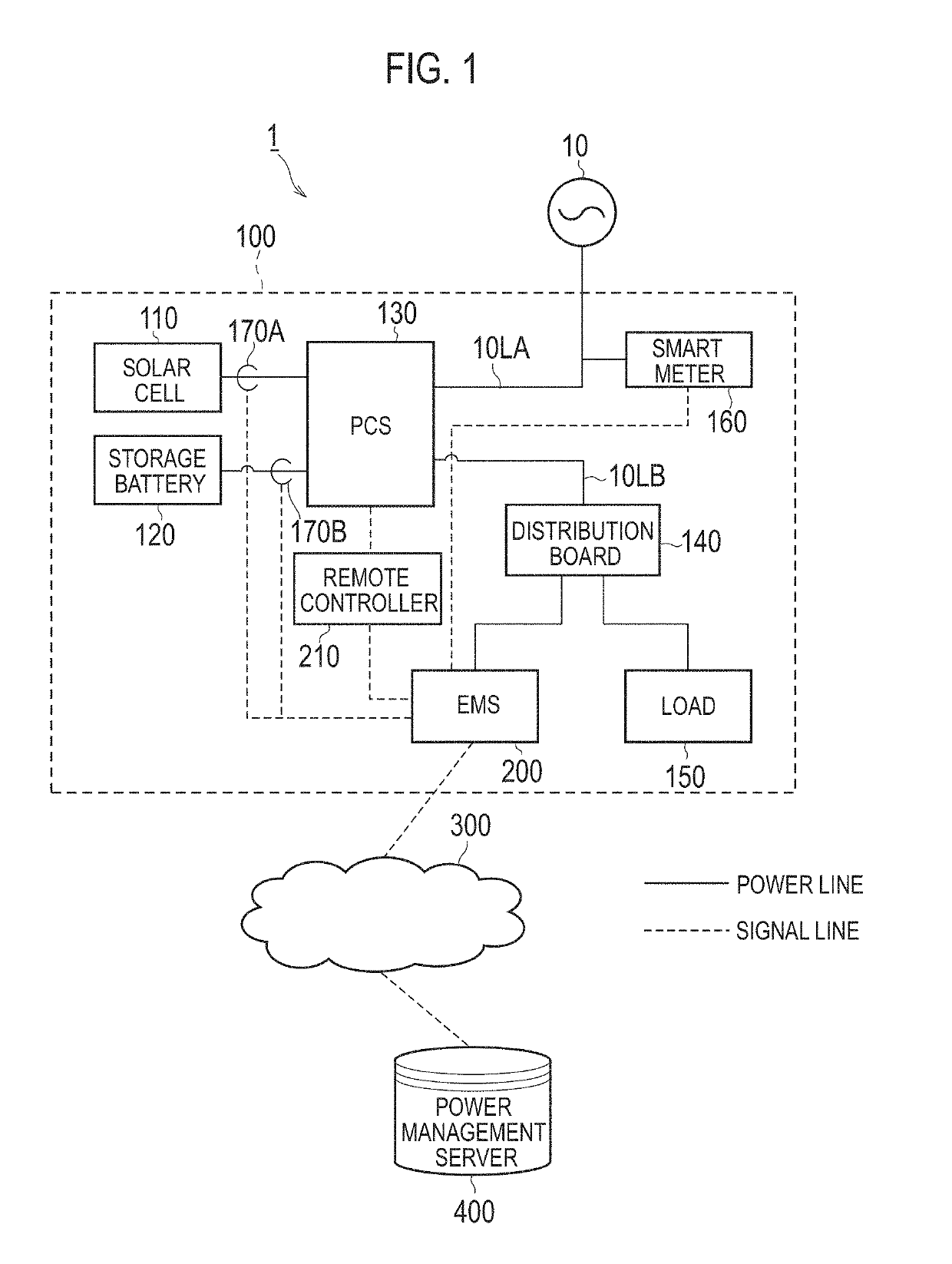
[0019]Hereinafter, a power management system according to an embodiment will be described. As shown in FIG. 1, a power management system 1 includes a facility 100 and a power management server 400. The facility 100 includes an EMS 200, and the EMS 200 communicates with the power management server 400 through a network 300.

[0020]The facility 100 includes a solar cell 110, a storage battery 120, a PCS 130, a distribution board 140, a load 150, a power meter (hereinafter, referred to as a smart meter) 160, and a sensor 170. Further, the facility 100 includes the EMS 200 and a remote controller 210. Although an example in which the power management system 1 includes the solar cell 110, the storage battery 120, the PCS 130, the distribution board 140, and the load 150 has been shown in FIG. 1, the power management system 1 is not limited to thereto, and any one of these components may be omitted.

[0021]The solar cell 110 is a photoelectric conversion apparat...

modified example 1

[0062]Hereinafter, Modified Example 1 of the embodiment will be described.

[0063]Portions different from those of the embodiment will mainly be described below.

[0064]Specifically, in Modified Example 1, a case where there is a need to perform the control the reverse power flow amount (the output power amount of the distributed power supply) as well as the control of the power flow amount in a section managed by the power management server 400 is assumed. In such a case, the power management server 400 transmits the power flow control message to the facility 100 in which the reverse power flow amount is not controlled at the time of determination.

[0065]Specifically, as shown in FIG. 5, a process of step S23A is added after step S23 in the flowchart shown in FIG. 4.

[0066]In step S23A, the power management server 400 determines whether or not the output control is being performed in the facility 100. When the output control is not being performed, a process of step S24 is performed. Whe...

modified example 2

[0068]Hereinafter, Modified Example 2 of the embodiment will be described. Portions different from those of the embodiment will mainly be described below.

[0069]In Modified Example 2, a case where an entity providing a power to the facility 100 is different from an entity purchasing a power from the facility 100 is exemplified. The entity providing the power to the facility 100 may be considered as an entity managing the power flow amount to the facility 100. The entity purchasing the power from the facility 100 may be considered as an entity managing the reverse power flow amount from the facility 100. Under such a premise, a case where the power management server belongs to the entity purchasing the power from the facility 100 is considered. The entity providing the power to the facility 100 may be a company such as a power generation company, a power transmission / distribution company, or a power retail company. The entity purchasing the power from the facility 100 may be a company...


PUM


Abstract

A power management apparatus includes a receiver configured to receive measurement information obtained by measuring a power of a facility connected to a power grid; and a transmitter configured to transmit a power control message. The transmitter transmits the power control message based on an output power amount of a distributed power supply provided in the facility, in addition to the measurement information. The measurement information is information indicating a total power flow amount from the power grid to the facility or a total reverse power flow amount from the facility to the power grid. The distributed power supply is a power supply that allows a reverse power flow from the facility to the power grid.

Description

RELATED APPLICATIONS[0001]The present application is a National Phase of PCT / JP2017 / 030378, filed Aug. 24, 2017, and claims priority based on Japanese Patent Application No. 2016-163616, filed Aug. 24, 2016.TECHNICAL FIELD[0002]The present invention relates to a power management server, a power management method, and a power management system.BACKGROUND ART[0003]In recent years, power suppression messages such as a power flow message requesting suppression of a power flow amount from a power grid to a facility and a reverse power flow message requesting suppression of a reverse power flow amount from the facility to the power grid have been known (see, for example, Patent Literatures 1 and 2).[0004]Under the background described above, a smart meter has been known as a power meter that measures a total power flow amount from the power grid to the facility or a total reverse power flow amount from the facility to the power grid. It is conceivable to predict a power demand-supply bala...

Claims


Application Information

Patent Timeline
Patent Type & Authority Applications(United States)
IPC IPC(8): H02J13/00H02J3/38G05B15/02
CPCH02J13/0006H02J3/383G05B15/02H02J3/00H02J3/38H02J13/00H02J3/381H02J13/00022H02J13/00002Y04S10/30Y04S40/126Y02E60/00Y04S10/12Y04S40/12Y02E40/70Y04S10/123H02J13/00006
Inventor OKINO, KENTA
Owner KYOCERA CORP
Why Eureka
Try Eureka