Surgical bandage with stabilizing elements
a technology of stabilizing elements and surgical bandages, applied in the field of bandages, can solve the problems of inability to make incisions or excision wounds through our claimed bandages, and the care of personals is to date not satisfactorily solved
- Summary
- Abstract
- Description
- Claims
- Application Information
AI Technical Summary
Problems solved by technology
Method used
Image

Examples
example 1
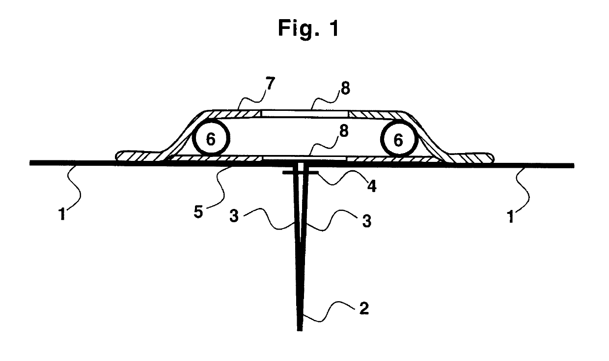
[0042]Referring to FIG. 1 the optional skin-contacting layer 5 is transparent, adhesive and permeable for liquids at least on an area covering the wound 2. The wound may e g be a surgical incision. Permeability may be achieved by mechanical means, such as small holes, a network or by the material of the skin-contacting layer 5 being permeable as such. The bandage comprises an optional skin-contacting layer 5, being at least partly perforated, e g with small openings, or provided with a network. Other configurations and combinations thereof are also possible. Any suitable material in the art may be used, e g polymeric material. Adhesion of the skin-contacting layer 5 to the skin 1 may be achieved by chemical means, e g adhesives, and / or by mechanical means, e g a high-friction surface and micro-hooks.
[0043]In order to keep the wound edges 3 well together the skin-contacting layer 5 is preferably elastic and stretchable. The skin-contacting layer 5 should preferably be stretched when ...
example 2
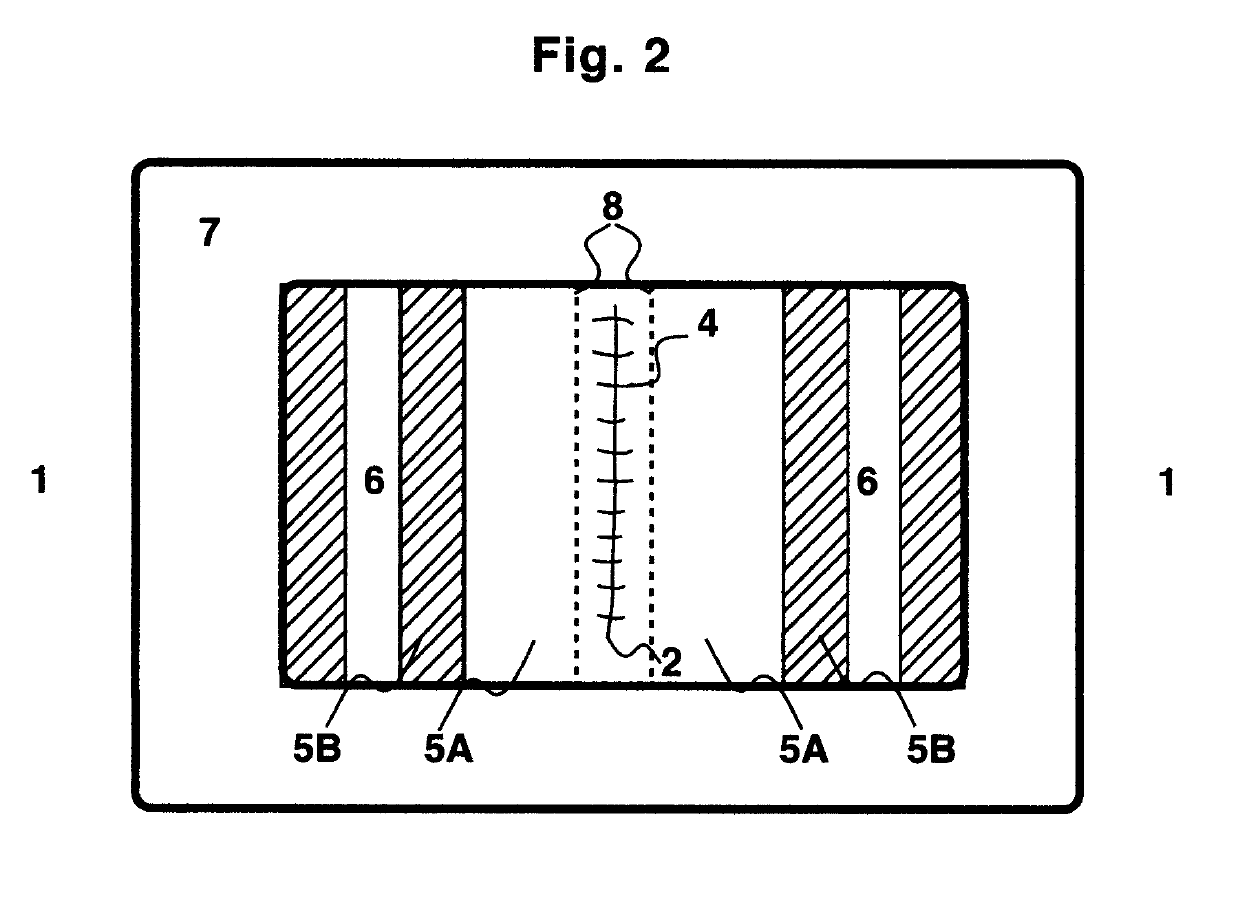
[0046]Elasticity of the skin-contacting layer 5 may be achieved by the material of the layer being elastic or stretchable as such. Referring to FIG. 2 the skin-contacting layer 5 may alternatively be transparent and permeable only on the part covering the wound 2 and optionally a little more. The remaining part of the skin-contacting layer 5 is elastic or stretchable, but need be neither transparent nor permeable. One advantage in using two, or possibly more, materials is that you get a wider choice of stretchable materials. The stabilizing element / s 6 may preferably absorb liquid, such as water, blood and blood components. The stabilizing element / s 6 serve / s a dual function. They may absorb liquid leaking from the wound 2. They may also transfer the pressure exercised on the wound 2, e g when a person with a dorsal wound is lying on his back, to an area of the skin 1 being outside the wound 2. This transfer of pressure increases perceived compliance and reduces recovery time.
[0047]...
example 3
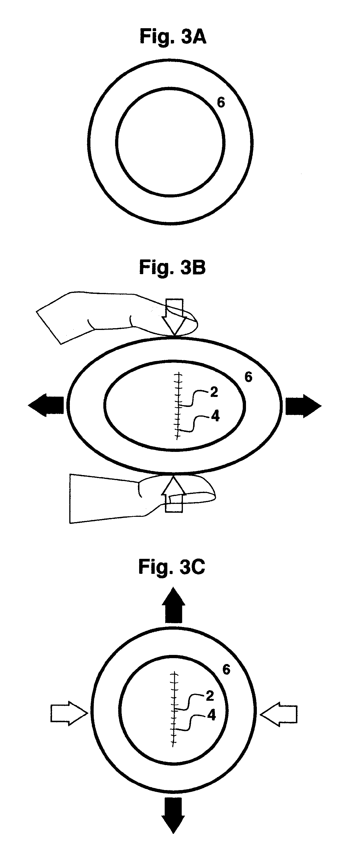
[0052]FIG. 3 shows a useful embodiment for keeping the wound edges 3 together. The stabilizing element / s 6 is / are an elastic and closed circular loop. Other forms of the stabilizing element / s 6 are envisageable, such as oval, rectangular, hexagonal or octagonal. The stabilizing element / s 6 is elastic in itself or is rendered elastic by other means, e g by being placed within an elastic plastic ring. The stabilizing element / s 6 can have different, but preferably symmetrical, cross sections, such as square, hexagonal, octagonal, circular, and oval or combinations thereof.
[0053]The present embodiment is to be used mainly according to stages A, B and C of FIG. 3. White arrows denote compression. Black arrows denote expansion.
[0054]Stage A: The stabilizing element / s 6 may e g form a circle when not being exercised. This stage A is the stage when the bandage is still in its package or simply prior to use.
[0055]Stage B: An optional release liner 9 is removed. The bandage is oriented over t...
PUM
 Abstract
Description
Claims
Application Information
 - R&D Engineer
- R&D Manager
- IP Professional
- Industry Leading Data Capabilities
- Powerful AI technology
- Patent DNA Extraction
Browse by: Latest US Patents, China's latest patents, Technical Efficacy Thesaurus, Application Domain, Technology Topic.
© 2024 PatSnap. All rights reserved.Legal|Privacy policy|Modern Slavery Act Transparency Statement|Sitemap