Lens device, imaging device, and focus shift correction method of lens device

a technology of lens device and imaging device, which is applied in the direction of camera focusing arrangement, printers, instruments, etc., can solve the problem of low degree of design freedom of imaging device, and achieve the effect of preventing the focus shift of an imaging optical system and reducing the degree of design freedom

Active Publication Date: 2019-06-20
FUJIFILM CORP
View PDF0 Cites 4 Cited by
  • Summary
  • Abstract
  • Description
  • Claims
  • Application Information

AI Technical Summary

Benefits of technology

[0015]According to the present invention, it is possible to provide a lens device capable of preventing a focus shift of an imaging optical system du

Problems solved by technology

Since the temperature sensor is directly attached to the infrared optic

Method used


Image

  • Lens device, imaging device, and focus shift correction method of lens device
  • Lens device, imaging device, and focus shift correction method of lens device
  • Lens device, imaging device, and focus shift correction method of lens device

Examples


Embodiment Construction

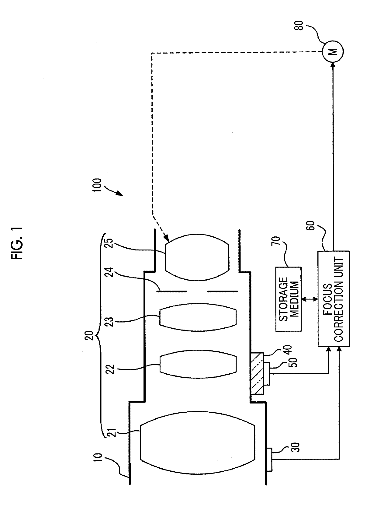
[0024]FIG. 1 is a schematic diagram showing a schematic configuration of a lens device 100 which is an embodiment of the present invention.

[0025]The lens device 100 comprises an imaging optical system 20, a lens barrel 10 which is made of metal such as aluminum or titanium and accommodates the imaging optical system 20, a temperature sensor 30 fixed onto an outer peripheral surface of the lens barrel 10, a member 40 which is fixed onto the outer peripheral surface of the lens barrel 10 and has a temperature characteristic different from that of the lens barrel 10, a temperature sensor 50 fixed onto the member 40, a focus correction unit 60, a storage medium 70, and a motor 80.

[0026]The lens device 100 is used while the lens barrel 10 is attached to the imaging device on which an imaging element (not shown) is mounted. In the imaging device to which the lens barrel 10 is attached, it is possible to obtain a captured image by imaging a subject by using the imaging element through the ...


PUM


Abstract

Provided are a lens device capable of preventing a focus shift of an imaging optical system due to heat without reducing a degree of freedom of design, an imaging device comprising the same, and a focus shift correction method of a lens device. A lens device 100 includes an imaging optical system 20 that includes a plurality of lenses, a lens barrel 10 that accommodates the imaging optical system 20, a temperature sensor 30 that is provided outside the lens barrel 10 to detect a temperature of the lens barrel 10, a temperature sensor 50 that is provided outside the lens barrel 10 to detect a temperature of a member 40 of which a temperature characteristic indicating a temperature change with a time change is different from a temperature characteristic of the lens barrel 10, and a focus correction unit 60 that corrects a focus shift of the imaging optical system 20 by controlling a relay lens 25 as a correction lens included in the imaging optical system 20 based on temperature information items respectively detected by the temperature sensor 30 and the temperature sensor 50.

Description

CROSS REFERENCE TO RELATED APPLICATION[0001]This is a continuation of International Application No. PCT / JP2017 / 017097 filed on Apr. 28, 2017, and claims priority from Japanese Patent Application No. 2016-171618 filed on Sep. 2, 2016, the entire disclosures of which are incorporated herein by reference.BACKGROUND OF THE INVENTION1. Field of the Invention[0002]The present invention relates to a lens device, an imaging device, and a focus shift correction method of a lens device.2. Description of the Related Art[0003]For example, a television camera is configured such that a lens device is connected to a camera main body. An imaging optical system included in this lens device includes a plurality of lenses. The plurality of lenses is built in within a lens barrel so as to have a predetermined positional relationship, and is supported by a lens support member within the lens barrel.[0004]There are some cases where a lens which causes a focus shift of the imaging optical system due to ex...

Claims


Application Information

Patent Timeline
IPC IPC(8): G02B7/02
CPCG02B7/028G03B3/10G03B13/36H04N3/00G03B1/00
Inventor WADA, TETSU
Owner FUJIFILM CORP
Why Eureka
Try Eureka