This helps you quickly interpret patents by identifying the three key elements:
Problems solved by technology
Method used
Benefits of technology
Benefits of technology
The patent describes a system and method for determining the orientation of a camera in a real-world environment using a map of the environment. The system includes an imaging device and a processor that obtain a current image of the environment and extract salient points from the image. These salient points are then matched with real-world locations in a map database to determine the position of the camera. The system can adjust the position of the camera based on the match and the descriptor-based map. The method can also include extracting second salient points from the current image and providing descriptors for them. The system can generate the map based on the imaging device and the position of the camera. The technical effects of this system and method include improved accuracy in determining camera position and orientation in augmented reality applications.
Problems solved by technology
Because the human visual perceptionsystem is complex, it is challenging to produce an AR technology that facilitates a comfortable, natural-feeling, rich presentation of virtual image elements amongst other virtual or real-world imagery elements.
Method used
Image
Click on the blue label to locate the original text in one second.
Reading with bidirectional positioning of images and text.
Examples
Embodiment Construction
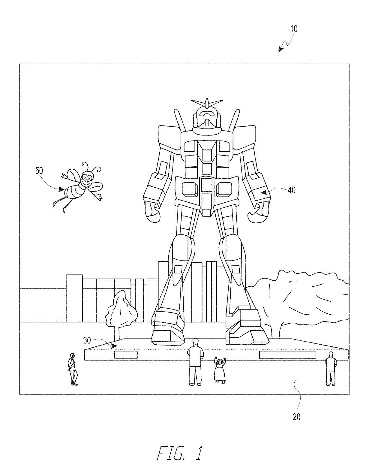
[0037]Display systems, such as augmented reality (AR) or virtual reality (VR) display systems, can present content to a user (or viewer) in differing areas of the user's field of view. For example, an augmented reality display system may present virtual content to the user, which to the user can appear to be placed in a real-world environment. As another example, a virtual reality display system can present content via displays, such that the content can appear to be three-dimensional to the user and placed within a three-dimensional environment. The placement of this content, for example with respect to the user, can positively or negatively affect the realism associated with the presented content, and the user's comfort in wearing the display system. Since the placement of content can be dependent on a head pose of users of the display systems, as will be described below, these display systems can be enhanced via utilization of accurate schemes to determine head pose.
[0038]The pos...
PUM
Abstract
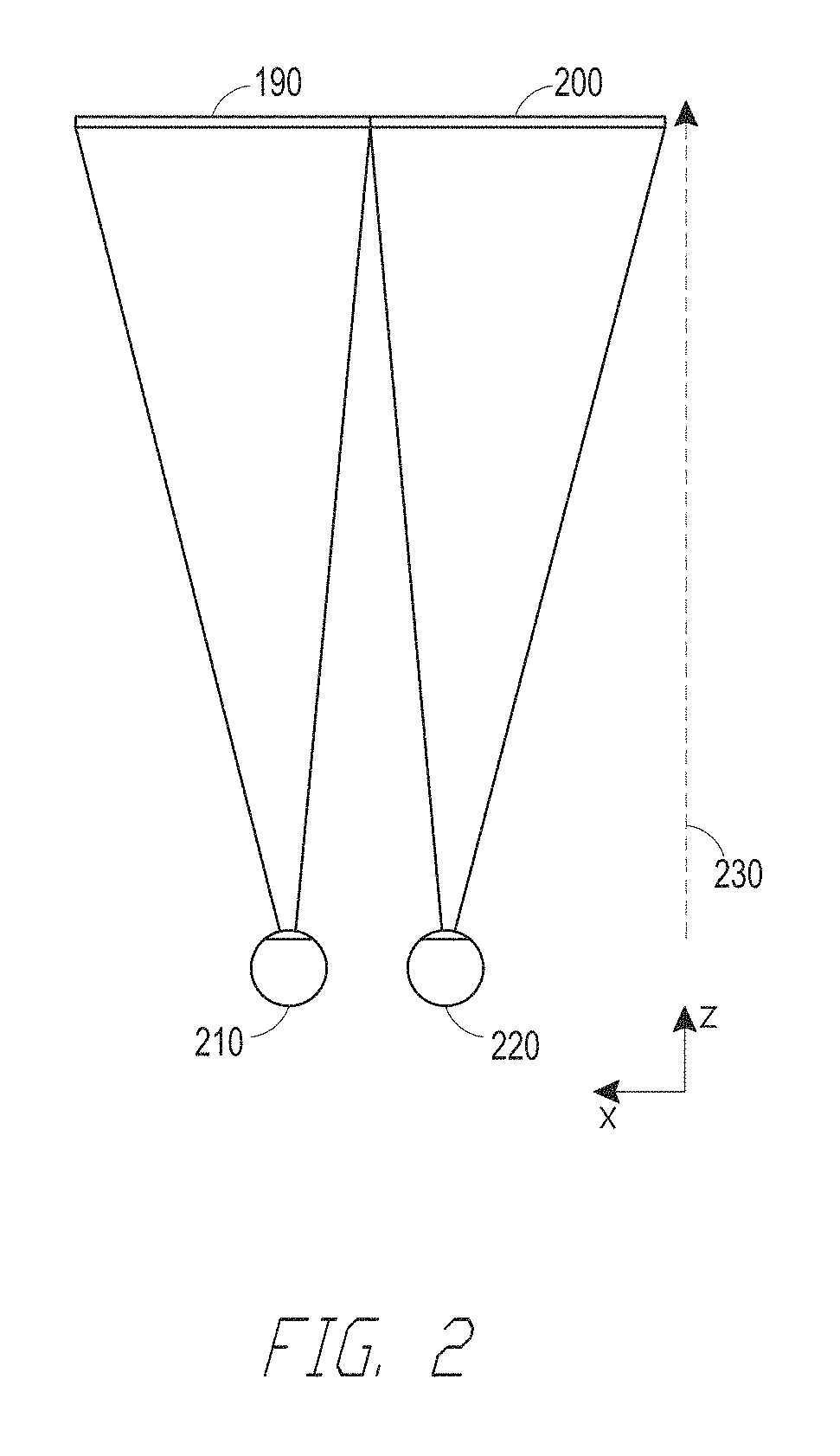
To determine the head pose of a user, a head-mounted display system having an imaging device can obtain a current image of a real-world environment, with points corresponding to salient points which will be used to determine the head pose. The salient points are patch-based and include: a first salient point being projected onto the current image from a previous image, and with a second salient point included in the current image being extracted from the current image. Each salient point is subsequently matched with real-world points based on descriptor-based map information indicating locations of salient points in the real-world environment. The orientation of the imaging devices is determined based on the matching and based on the relative positions of the salient points in the view captured in the current image. The orientation may be used to extrapolate the head pose of the wearer of the head-mounted display system.
Description
INCORPORATION BY REFERENCE[0001]This application claims priority to U.S. Prov. App. 62 / 599,620, filed Dec. 15, 2017, and U.S. Prov. App. 62 / 623,606, filed Jan. 30, 2018. Each of these applications is hereby incorporated by reference in its entirety.[0002]This application further incorporates by reference the entirety of each of the following patent applications: U.S. application Ser. No. 14 / 555,585 filed on Nov. 27, 2014, published on Jul. 23, 2015 as U.S. Publication No. 2015 / 0205126; U.S. application Ser. No. 14 / 690,401 filed on Apr. 18, 2015, published on Oct. 22, 2015 as U.S. Publication No. 2015 / 0302652; U.S. application Ser. No. 14 / 212,961 filed on Mar. 14, 2014, now U.S. Pat. No. 9,417,452 issued on Aug. 16, 2016; U.S. application Ser. No. 14 / 331,218 filed on Jul. 14, 2014, published on Oct. 29, 2015 as U.S. Publication No. 2015 / 0309263; U.S. application Ser. No. 14 / 205,126, filed Mar. 11, 2014, published on Oct. 16, 2014 as U.S. Publication No. 2014 / 0306866; U.S. application...
Claims
Application Information
Patent Timeline
Application Date:The date an application was filed.
Publication Date:The date a patent or application was officially published.
First Publication Date:The earliest publication date of a patent with the same application number.
Issue Date:Publication date of the patent grant document.
PCT Entry Date:The Entry date of PCT National Phase.
Estimated Expiry Date:The statutory expiry date of a patent right according to the Patent Law, and it is the longest term of protection that the patent right can achieve without the termination of the patent right due to other reasons(Term extension factor has been taken into account ).
Invalid Date:Actual expiry date is based on effective date or publication date of legal transaction data of invalid patent.
InventorZAHNERT, MARTIN GEORGFARO, JOAO ANTONIO PEREIRAVELASQUEZ, MIGUEL ANDRES GRANADOSKASPER, DOMINIK MICHAELSWAMINATHAN, ASHWINMOHAN, ANUSHSINGHAL, PRATEEK

