
Foldable firearm

Active Publication Date: 2019-06-27
MAGPUL INDUSTRIES
View PDF0 Cites 11 Cited by
  • Summary
  • Abstract
  • Description
  • Claims
  • Application Information

AI Technical Summary

Benefits of technology

The patent describes a foldable firearm with a unique charging handle assembly and a slide racking assembly. The charging handle assembly has two rotatably coupled charging handles that can be moved in a perpendicular orientation about the firearm. The slide racking assembly can move parallel to the firearm in concert with the charging handles. The foldable firearm can be easily converted from a folded to an unfolded configuration by pivoting the charging handles. The technical effects of this invention include improved ergonomics, compact design, and enhanced functionality.

Problems solved by technology

However, this process required some disassembly of the firearm.

Method used


Image

  • Foldable firearm
  • Foldable firearm
  • Foldable firearm

Examples


first embodiment

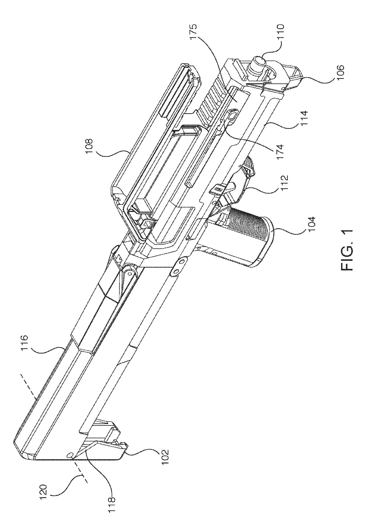
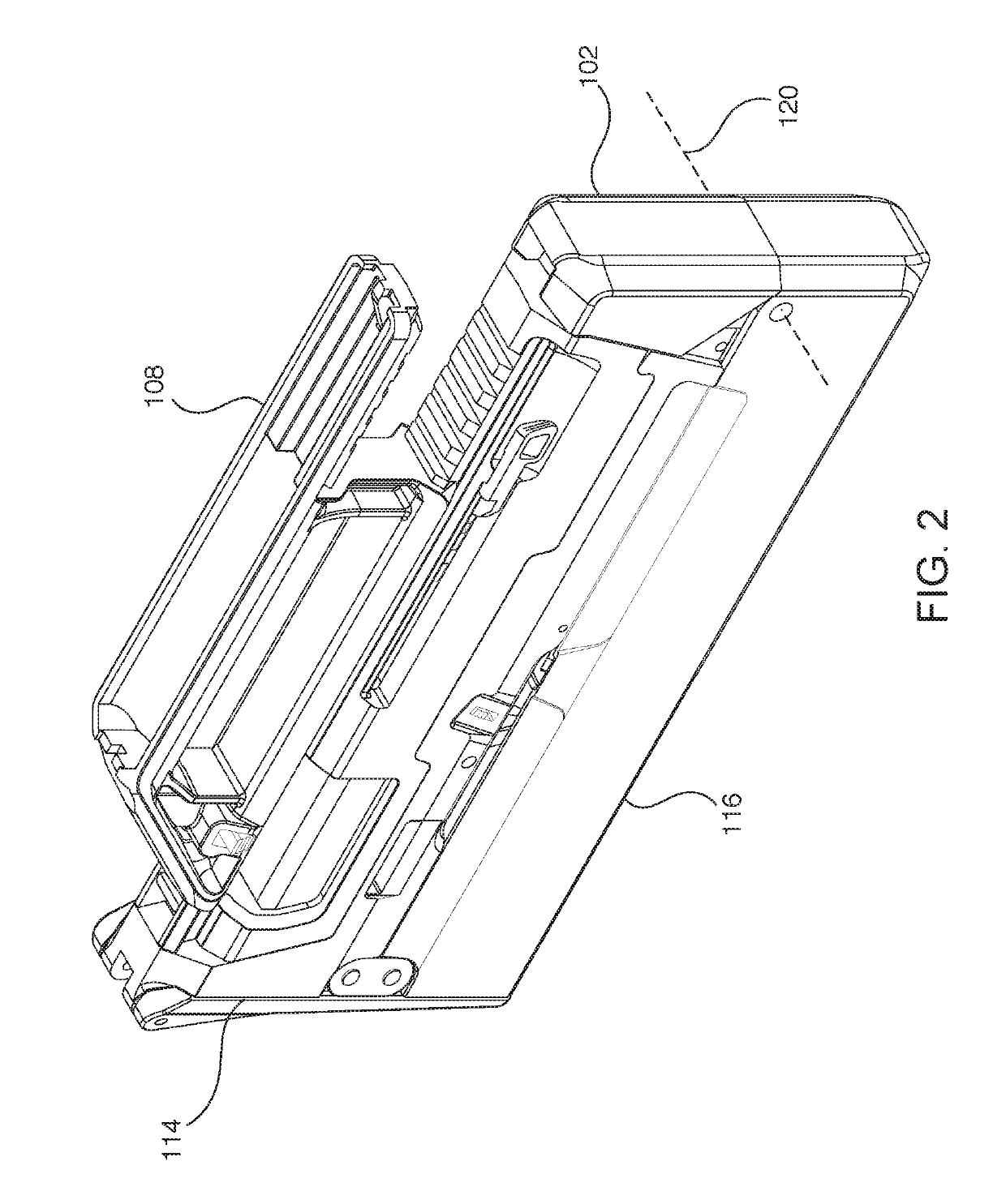
[0080]First charging handle 172 and second charging handle 174 may initiate unfolding of foldable firearm 100. the unfolding of foldable firearm 100 comprises pulling either first charging handle 172 or second charging handle 174 towards the rear of foldable firearm 100 while the charging handle is in a flush orientation. The pulled charging handle may cause the ambidextrous charging handle assembly 170 to move rearwards at a distance less than D1 (as discussed in relation to, and illustrated in, FIG. 40 above). This may cause tab 179 to lose contact with bottom shell 116 and bottom shell 116 may rotate downward (i.e., deploy) under spring pressure (as discussed in relation to, and illustrated in, FIG. 5 above). In this embodiment, the charging handle is not pivoted, but merely pulled parallel to a longitudinal axis of the firearm 100. Thus, racking of slide 150 is not possible in this configuration as ambidextrous charging handle assembly 170 has not moved distance D1 in order for ...

second embodiment

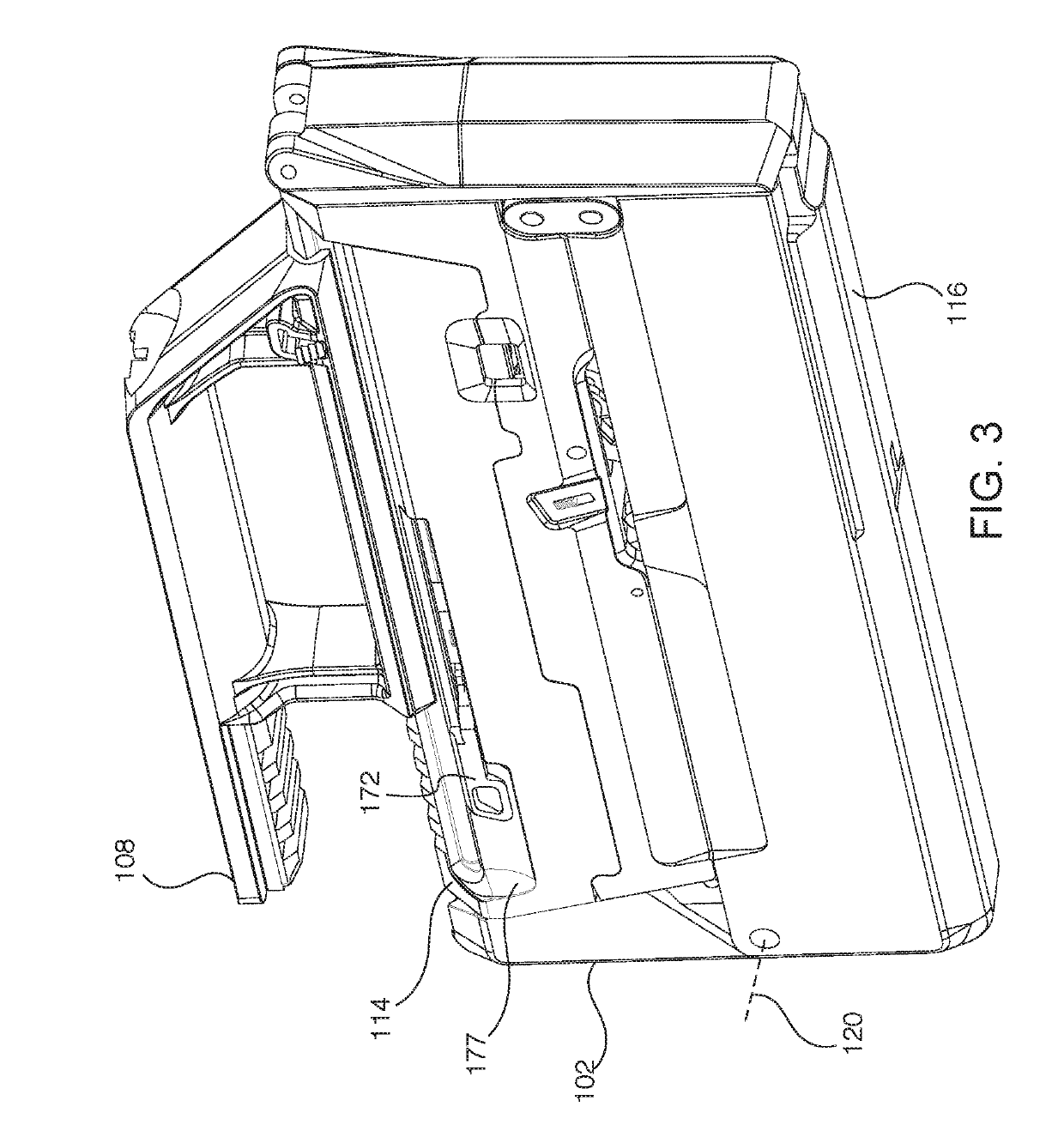
[0081]unfolding foldable firearm 100 comprises pivoting either first charging handle 172 or second charging handle 174 about its pivot axis, “butterflying” the charging handle outwards. The initiating charging handle can pivot a certain degree before engaging with the opposing charging handle and starting to cause that charging handle to also butterfly. Alternatively, the charging handles can interface such that butterflying of one charging handle immediately causes butterflying of the opposing charging handle. When either charging handle is moved rearward (either in a butterflied or flush orientation to the top shell 114) more than D1, the slide racking detents 190 contact the front of slide 150. Pivoting either charging handle such that the large detent of the pivoted charging handle contacts the opposing charging handle's small detent may cause the opposing charging handle to pivot about its pivot axis, thus butterflying the opposing charging handle (discussed further in relation...

third embodiment

[0097]FIG. 13 illustrates a foldable firearm with a third hinged tail, the hinged tail inclusive of a bracing strap or apertures to affix a bracing strap. The foldable firearm is here illustrated in a folded state. The third hinged tail 128 has the same shape as the first hinged tail 102, but adds apertures 130 or other attachment points for a bracing strap (e.g., see FIG. 29). The bracing strap can be wrapped around an arm, shoulder, or torso of a user, to enhance shooting accuracy and reduce the effects of kickback when the foldable firearm is fired.

[0098]FIG. 14 illustrates a deployed view of the foldable firearm of FIG. 13.

[0099]FIG. 15 illustrates an embodiment of a foldable firearm with the first hinged tail, in a folded state, but without a carrying handle.

[0100]FIG. 29 illustrates an embodiment of a foldable firearm with a combination of the second and third hinges, plus an exemplary bracing strap. The bracing strap passes through strap apertures near a bottom of the hinged ...


PUM


Abstract

The present disclosure describes a foldable firearm that collapses into a folded state under spring pressure. The foldable firearm may include a foldable grip assembly. The foldable grip assembly may include a foldable pistol grip, a foldable trigger assembly, a folding bar, and a foldable hand stop. The foldable grip assembly may fold into the top shell of the foldable firearm. The foldable firearm may also include an ambidextrous charging handle assembly that may include a bottom portion, a top portion, a guide bar, and two opposing charging handles. The charging handles may be pulled to unfold the foldable firearm, and / or butterflied such that pivoting one charging handle causes the other charging handle to pivot. The first-pivoted charging handle may then be pulled rearwards to unfold the firearm. The first-pivoted charging handle may then be pulled further rearwards to rack the slide of the foldable firearm.

Description

CROSS REFERENCE TO RELATED APPLICATIONS[0001]The present application for patent claims priority to U.S. Provisional Application No. 62 / 610,731, entitled “ARM BRACE FOR PISTOL,” filed Dec. 27, 2017, the entire disclosure of which is hereby incorporated by reference for all proper purposes.FIELD OF DISCLOSURE[0002]The present disclosure relates generally to handheld firearms, and more specifically to a foldable handheld firearm which may include a charging handle assembly and / or a foldable grip assembly to enable folding and unfolding of the foldable firearm.DESCRIPTION OF RELATED ART[0003]Folding firearms such as MAGPUL'S FMG-9, the ARES / Warin Stealth Gun, UC-9 and M-21, PP-90 and Goblin are exemplary of folding handheld firearms. Historically these handled firearms were of a submachinegun design. These firearms utilized a folding cover as a butt stock providing shoulder support when deployed. Even if rudimentary as compared to typical rifle stocks, they provided stability and suppor...

Claims


Application Information

Patent Timeline
IPC IPC(8): F41C23/04F41C23/12F41A35/06F41C33/08
CPCF41C23/04F41C23/12F41A35/06F41C33/08F41A11/04F41A3/66F41C9/02F41A3/72
Inventor KIELSMEIER, NICHOLASNAKAYAMA, BRIAN L.FIESTER, JEREMYMAYBERRY, MICHAEL T.
Owner MAGPUL INDUSTRIES
Learn More