
Machine geometry monitoring

a technology of machine geometry and monitoring, applied in the direction of mechanical measuring arrangement, instruments, image feed-back, etc., can solve the problems of non-reproducible or non-reversible repeatable long-term effects, deviations that cannot be reproduced or repeated in time, and the actual effect of the overall machine geometry cannot always be predicted accurately

Active Publication Date: 2019-06-27
HEXAGON TECH CENT GMBH
View PDF0 Cites 9 Cited by
  • Summary
  • Abstract
  • Description
  • Claims
  • Application Information

AI Technical Summary

Benefits of technology

The present invention aims to provide a device and method for monitoring deviations in geometric machine properties, particularly those with long time constants caused by temperature, shape changes, and other drift-effects. The device uses a global and preferably absolute sensing to measure these deviations and can take into account the machine's temperature and shape. This allows for real-time compensation to minimize or overcome the effects of non-repeatable events. By providing a low frequency global surveillance system, the invention allows for minimizing or overcoming those effects that would otherwise impact the machine's performance.

Problems solved by technology

Especially if measurements have to be performed inline in a process chain on a shop floor, the environment can be quite harsh and more error prone than in dedicated, air-conditioned and specifically designed measurement facilities.
Although temperatures can be measured, their actual effect on the overall machine geometry can not always be predicted accurately from those temperature values alone.
Many of those deviations are non-reproducible or non-reversible repeatable long term effects, due to climate changes, machine or environmental load conditions, settlement, wear, etc.
As said, it is known practice to calibrate a machine by sampling one or more reference balls, but such is time consuming and burdensome and not practical to be done often, in particular not in a shop floor environment.

Method used


Image

  • Machine geometry monitoring
  • Machine geometry monitoring
  • Machine geometry monitoring

Examples


Embodiment Construction

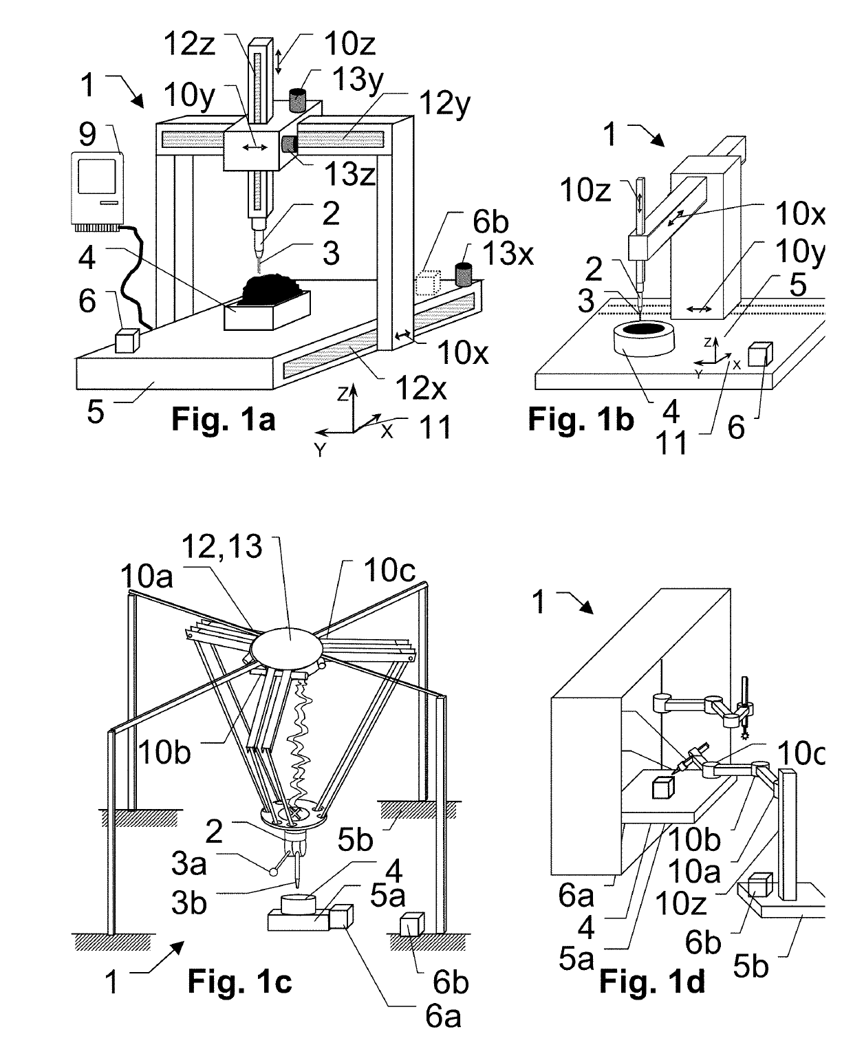
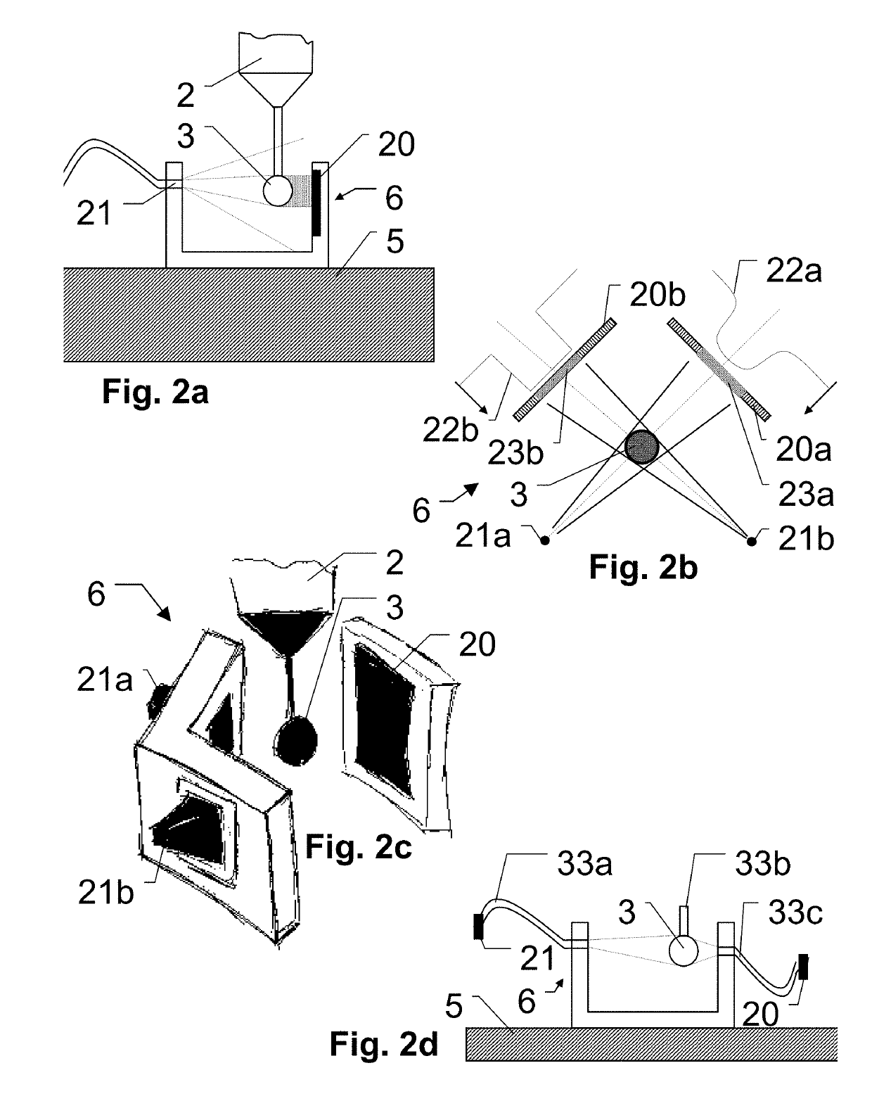
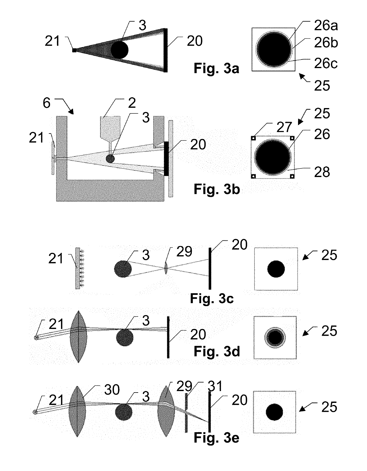
[0095]The diagrams of the figures should not be considered as being drawn to scale. Where appropriate, the same reference signs are used for the same features or for features with similar functionalities. Different indices to reference signs are used to differentiate between different embodiments of the same or an equivalent feature that is shown exemplary. The term “substantially” is herein used to describe the fact that that a certain value, arrangement or feature does not necessarily need to be 100% exact, but can maybe slightly aberrate, while still being within scope. In other words, there can be some slight deviations, e.g. due to inaccuracies, unintentional, design considerations, tolerances, etc.—but there is a clear tendency towards the mentioned value or arrangement, in particular in view of the technical effect to be achieved therewith. Especially, it is not meant to be an obvious opposite. In any case, besides the meaning of “almost exactly” the term “substantially” can ...


PUM


Abstract

A machine state monitoring system for recurrently determining a change in static or dynamic properties of a geometry of a machine with positional encoders to derive a coordinate information of at least a first machine portion with respect to a second machine portion, which are movable with respect to one another. The monitoring system includes one calibration-monitoring-unit with an optical, at least two-dimensional measuring location sensing unit which is fixed to the first machine portion and configured to optically sense an at least two dimensional location information of an artifact which is provided at the second machine portion, and temporarily moved into a sensing range for determining the change in the static or dynamic properties of the geometry of the machine by a comparison of multiple of such sensings, the compensation parameters are then updated and is used to derive the coordinate information from the encoders.

Description

CROSS-REFERENCE TO RELATED APPLICATIONS[0001]This application claims priority to European Patent Application No. 17209643.9, filed on Dec. 21, 2017. The foregoing patent application are incorporated herein by reference.FIELD OF INVENTION[0002]The present invention relates generally to a system or method for monitoring a machine geometry, respectively of sensing deviations in geometric properties of a machine during the machines usage, calibration monitoring units and computer programs.BACKGROUND[0003]Machines often require precise positioning of a machine portion with respect to another, for example coordinate measurement machines (herein also abbreviated as CMM) are often industrially used to measure geometrical features of objects. Therein the demanded accuracy is often rather high, e.g. in the range of micrometers or below. To achieve such, the CMMs are often built rigidly or quasi rigid, with high resolution positional encoders to accurately determine a position of a measurement...

Claims


Application Information

Patent Timeline
IPC IPC(8): G01B21/04G06T1/00G06K9/62G01B5/008G01B5/00
CPCG01B21/042G06T1/0014G06K9/6289G01B5/008G01B5/0014G06K2209/19G01B11/24G01B11/2441G01B11/2433G06V2201/06G06F18/251
Inventor ISELI, CLAUDIOSTIGWALL, JOHNJENSEN, THOMASPRZYGODDA, FRANK
Owner HEXAGON TECH CENT GMBH
Learn More