Capacitor module

a capacitor and module technology, applied in the field of capacitor modules, can solve the problems of thermal interference between adjacent capacitors and thermal interference, and achieve the effect of minimizing thermal interference between capacitors

Active Publication Date: 2019-06-27
DENSO CORP
View PDF13 Cites 2 Cited by
  • Summary
  • Abstract
  • Description
  • Claims
  • Application Information

AI Technical Summary

Benefits of technology

[0006]It is an object of this disclosure to provide a capacitor module

Problems solved by technology

The capacitor module equipped with the capacitors arranged therein has a drawback in that thermal interference occurs between every adjacent two of the capacitors, in other words, arrangement of the capacitors which are sealed close to each other within the capacitor case

Method used


Image

  • Capacitor module
  • Capacitor module
  • Capacitor module

Examples


first embodiment

[0037]The capacitor module 1 according to an embodiment will be described below with reference to FIGS. 1 to 10.

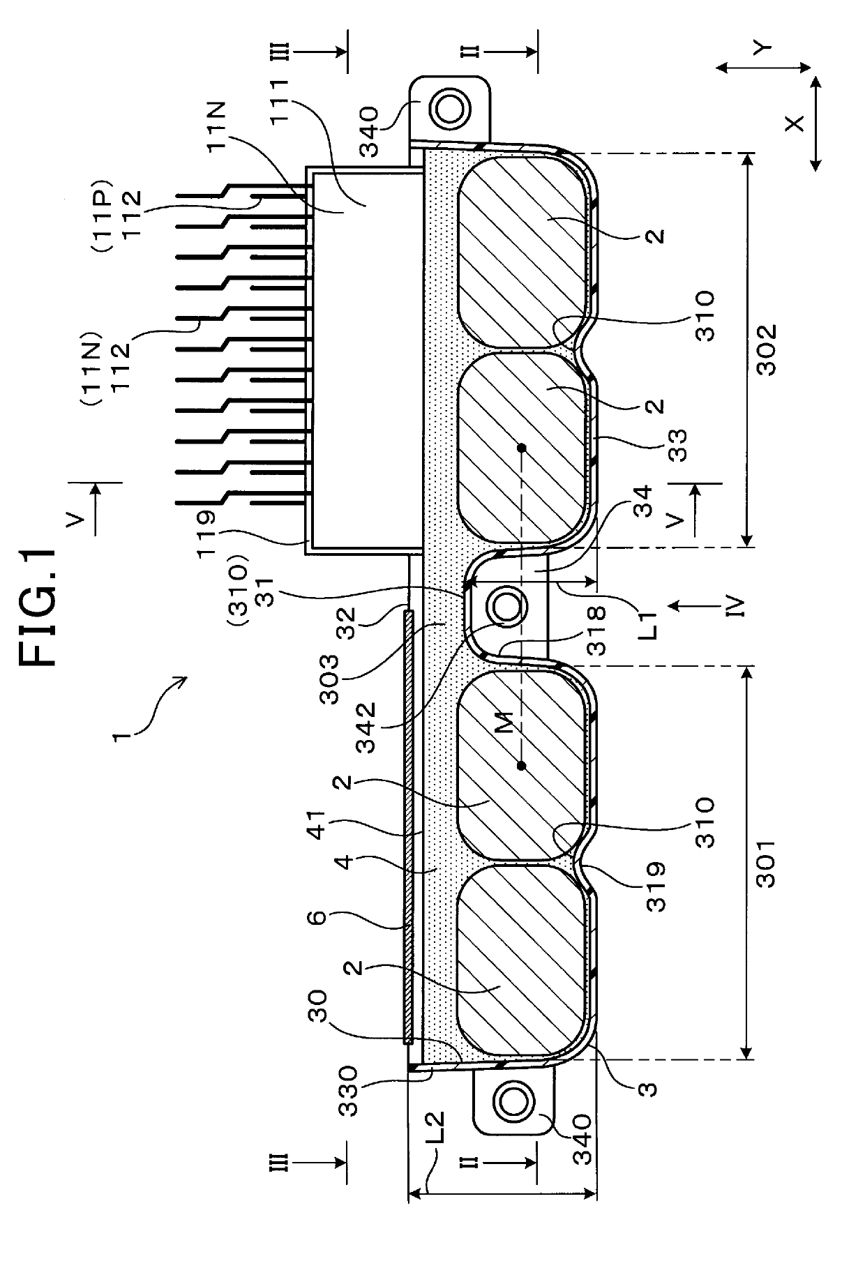
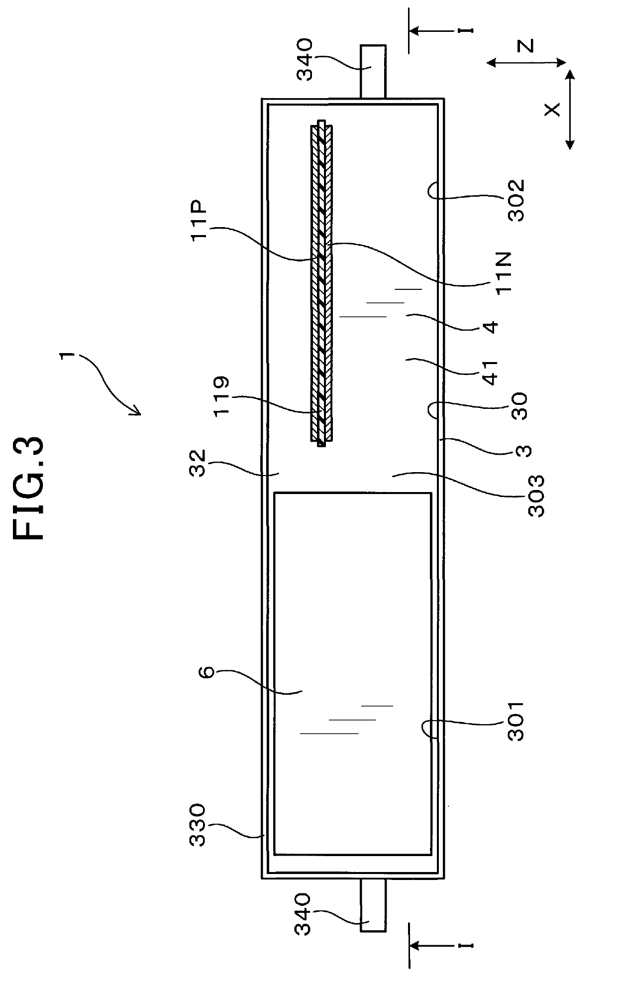
[0038]The capacitor module 1, as clearly illustrated in FIGS. 1 and 2, includes a plurality of capacitors 2, the capacitor case 3, and the sealing resin 4. The capacitor case 3 has the capacitors 2 mounted therein. The capacitor case 3 is filled with the sealing resin 4 to hermetically seal the capacitors 2 within the capacitor case 3.

[0039]The capacitor case 3 has the inward-facing portion 310 disposed between every adjacent two of the capacitors 2. Each of the inward-facing portions 310 is formed by a portion of an outer wall of the capacitor case 3 which protrudes or bulges inwardly between the adjacent capacitors 2.

[0040]The inward-facing portions 310 include at least one intervening inward-facing portion 31 in the following way. Specifically, as viewed in the height-wise direction Z, the intervening inward-facing portion 31 is one of the inward-facing portions 310 sha...

second embodiment

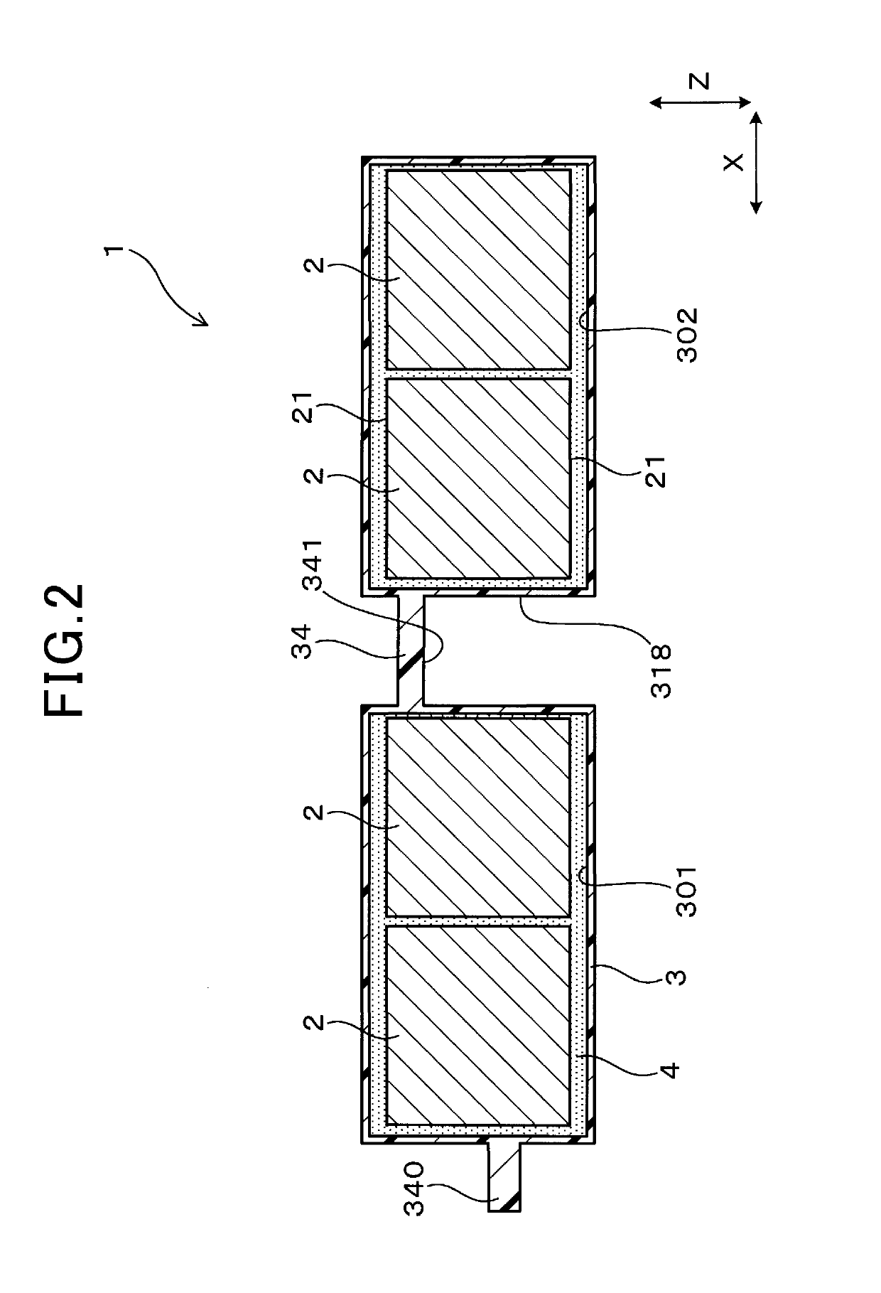
[0082]The capacitor module 1 in the second embodiment, as illustrated in FIGS. 11 to 14, has the contacting surface 341 of the fastening portion 34 which faces in the direction Y. Specifically, the contacting surface 341 faces in a direction opposite a direction in which the intervening inward-facing portion 31 protrudes.

[0083]The metallic member 342 is insert-molded with the capacitor case 3 so as to have an axis thereof oriented in the direction Y.

[0084]The metallic member 342 has a first end that is a lower one, as viewed in FIG. 11, of ends opposed to each other in an axial direction thereof. The first end is, as clearly illustrated in FIGS. 11 and 13, exposed outside the capacitor case 3 and faces away from the open surface 32 in the direction Y. The first end forms at least a portion of the contacting surface 341 of the fastening portion 34. The metallic member 342, as can be seen in FIGS. 11 and 12, also has a second end that is an upper one of the ends thereof, as viewed in ...

third embodiment

[0092]The capacitor module 1 in the third embodiment has the capacitor case 3 which is, as illustrated in FIG. 15, equipped with a plurality of heat dissipating fins 317 disposed on an outer surface of the intervening inward-facing portion 31. The heat dissipating fins 317 protrude from an outer wall of the capacitor case 3 which forms the intervening inward-facing portion 31 into the outer recess 318.

[0093]The heat dissipating fins 317 is formed integrally with resin making up the outer wall of the capacitor case 3.

[0094]Other arrangements of the capacitor module 1 are the same as those in the first embodiment.

[0095]The use of the heat dissipating fins 317 arranged on the outer surface of the intervening inward-facing portion 31 enhances the dissipation of heat from the capacitor module 1. Specifically, the capacitor module 1 of this embodiment is designed to have heat releasing paths extending from the intervening inward-facing portion 31 disposed between the two adjacent capacito...


PUM


Abstract

A capacitor module is provided which includes a plurality of capacitors, a capacitor case, and a sealing resin with which the capacitor case is filled to seal the capacitors in the capacitor case. The capacitor case includes inward-facing portions of an outer wall thereof each of which bulges or protrudes between every adjacent two of the capacitors. As viewed in a height-wise direction perpendicular both to a direction in which the inward-facing portions protrude and to a direction in which two of the capacitors adjacent each other across one of the inward-facing portions are aligned, the intervening inward-facing portion traverses a line segment passing through centers of the two adjacent capacitors. This structure minimizes thermal interference between the capacitors.

Description

CROSS REFERENCE TO RELATED DOCUMENT[0001]The present application claims the benefit of priority of Japanese Patent Application No. 2017-251932 filed on Dec. 27, 2017, the disclosure of which is incorporated herein by reference.BACKGROUND1 Technical Field[0002]This disclosure relates generally to a capacitor module made up of a plurality of capacitors.2 Background Art[0003]Japanese Patent First Publication No. 2014-68449 discloses an electric power converter which has installed therein a capacitor module equipped with a plurality of capacitors. The capacitor module includes a capacitor case in which the capacitors are installed and hermetically sealed by resin.[0004]The capacitor module equipped with the capacitors arranged therein has a drawback in that thermal interference occurs between every adjacent two of the capacitors, in other words, arrangement of the capacitors which are sealed close to each other within the capacitor case results in thermal interference between the adjace...

Claims


Application Information

Patent Timeline
IPC IPC(8): H01G4/258H01G4/224H01G4/38
CPCH01G4/258H01G4/224H01G4/38H01G2/08H01G4/32
Inventor KANDA, TAKAYUKIHAMAJIMA, DAIGO
Owner DENSO CORP
Why Eureka
Try Eureka