
Compensation table compressing method

a compression method and compensation table technology, applied in the field of compensation table compression method, can solve the problem that the compression ratio of compensation table and time complexity cannot meet actual demands, and achieve the effect of improving compression quality and reducing the compression ratio of compensation table and time complexity

Active Publication Date: 2019-06-27
SHENZHEN CHINA STAR OPTOELECTRONICS SEMICON DISPLAY TECH CO LTD
View PDF0 Cites 9 Cited by
  • Summary
  • Abstract
  • Description
  • Claims
  • Application Information

AI Technical Summary

Benefits of technology

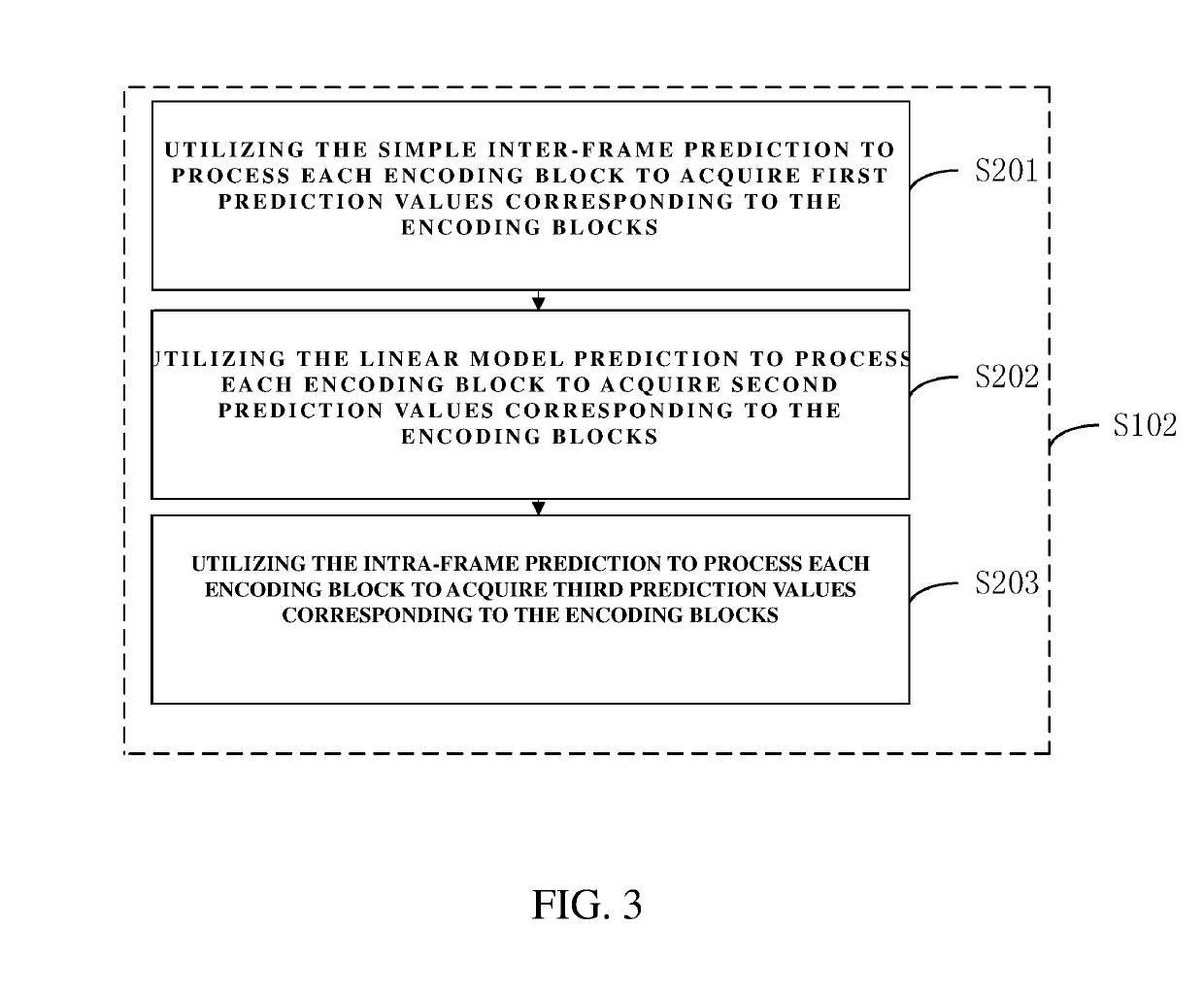
The present invention provides a compensation table compressing method that reduces the size of compensation tables and the time required for compression. This method uses prediction modes, such as simple inter-frame prediction, linear model prediction, and intra-frame prediction, to optimize the prediction process. By selecting the prediction mode with the highest quality for each encoding block, the method minimizes the loss of quality during compression. In summary, this method improves the quality of compensation table compression while reducing the complexity of the encoding process.

Problems solved by technology

Because different encoding tools in the encoder have different influences on the performance of the compensation table, which results in that encoding time complexity cannot meet actual demands.

Method used


Image

  • Compensation table compressing method
  • Compensation table compressing method
  • Compensation table compressing method

Examples


Embodiment Construction

[0080]The technical solution in the embodiment of the present invention will be clearly and completely described below with reference to the accompanying drawings in the embodiments of the present invention. Apparently, the described embodiments are merely some embodiments of the present invention instead of all embodiments. According to the embodiments in the present invention, all other embodiments obtained by those skilled in the art without making any creative effort shall fall within the protection scope of the present invention.

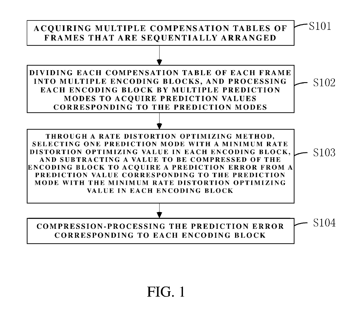
[0081]With reference to FIG. 1, FIG. 1 is a schematic view of a step flowchart of a compensation table compressing method provided by an embodiment of the present invention. As shown in FIG. 1, the embodiment of the present invention provides a compensation table compressing method, including steps as follows:

[0082]step S101, including acquiring multiple compensation tables of frames that are sequentially arranged;

[0083]step S102, including dividing eac...


PUM


Abstract

A compensation table compressing method is provided, processes each encoding block by prediction modes and select one prediction mode with the minimum rate distortion optimizing value as an optimized prediction mode by the rate distortion optimizing method such that each encoding block can correspond to an optimized prediction mode, which lowers the compression ratio of the compensation table and the time complexity of encoding and increases the quality of compression.

Description

FIELD OF THE INVENTION[0001]The present invention relates to display technology fields, especially to a compensation table compressing method.BACKGROUND OF THE INVENTION[0002]In the prior art, to eliminate the uneven brightness caused by a display panel, a compensation table is usually used to store compensation information of each pixel in the display panel such that the uneven brightness caused by the display panel is eliminated and display quality of the display panel is improved. In order to improve data transmission efficiency, the compensation tables need to be compressed[0003]At present, compression of the compensation tables usually directly employs a common universal encoder to compress the compensation tables. Because different encoding tools in the encoder have different influences on the performance of the compensation table, which results in that encoding time complexity cannot meet actual demands.SUMMARY OF THE INVENTION[0004]An objective of an embodiment of the presen...

Claims


Application Information

Patent Timeline
Patent Type & Authority Applications(United States)
IPC IPC(8): H04N19/159H04N19/176H04N19/182H04N19/105G09G3/20
CPCH04N19/159H04N19/176H04N19/182H04N19/105G09G3/20G09G2320/0285G09G2320/0242G09G3/3208H04N19/186H04N19/147
Inventor DENG, YUFANJOU, MING-JONGSYU, SHEN-SIAN
Owner SHENZHEN CHINA STAR OPTOELECTRONICS SEMICON DISPLAY TECH CO LTD
Learn More