A lifting assembly and method

Active Publication Date: 2019-07-04
BALLTEC
View PDF0 Cites 2 Cited by
  • Summary
  • Abstract
  • Description
  • Claims
  • Application Information

AI Technical Summary

Benefits of technology

[0034]The method allows a lifting configuration to be changed, for exam

Problems solved by technology

However, this is not possible with conventional structures as they are provided with a single set of fixed pad eyes.
As such, if, for example, the position of a load carried by the structure is altered then the padeyes may be subjected to an adverse bending moment during a lifting or lowering operation.
Consequently some existing structures are deliberately

Method used


Image

  • A lifting assembly and method
  • A lifting assembly and method
  • A lifting assembly and method

Examples


Embodiment Construction

[0042]In order that the invention may be more clearly understood embodiments thereof will now be described, by way of example only, with reference to the accompanying drawings, of which:

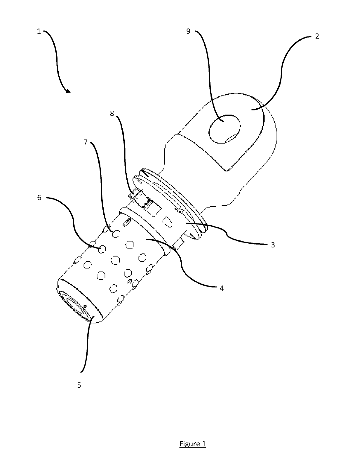
[0043]FIG. 1 is a perspective view of a connector;

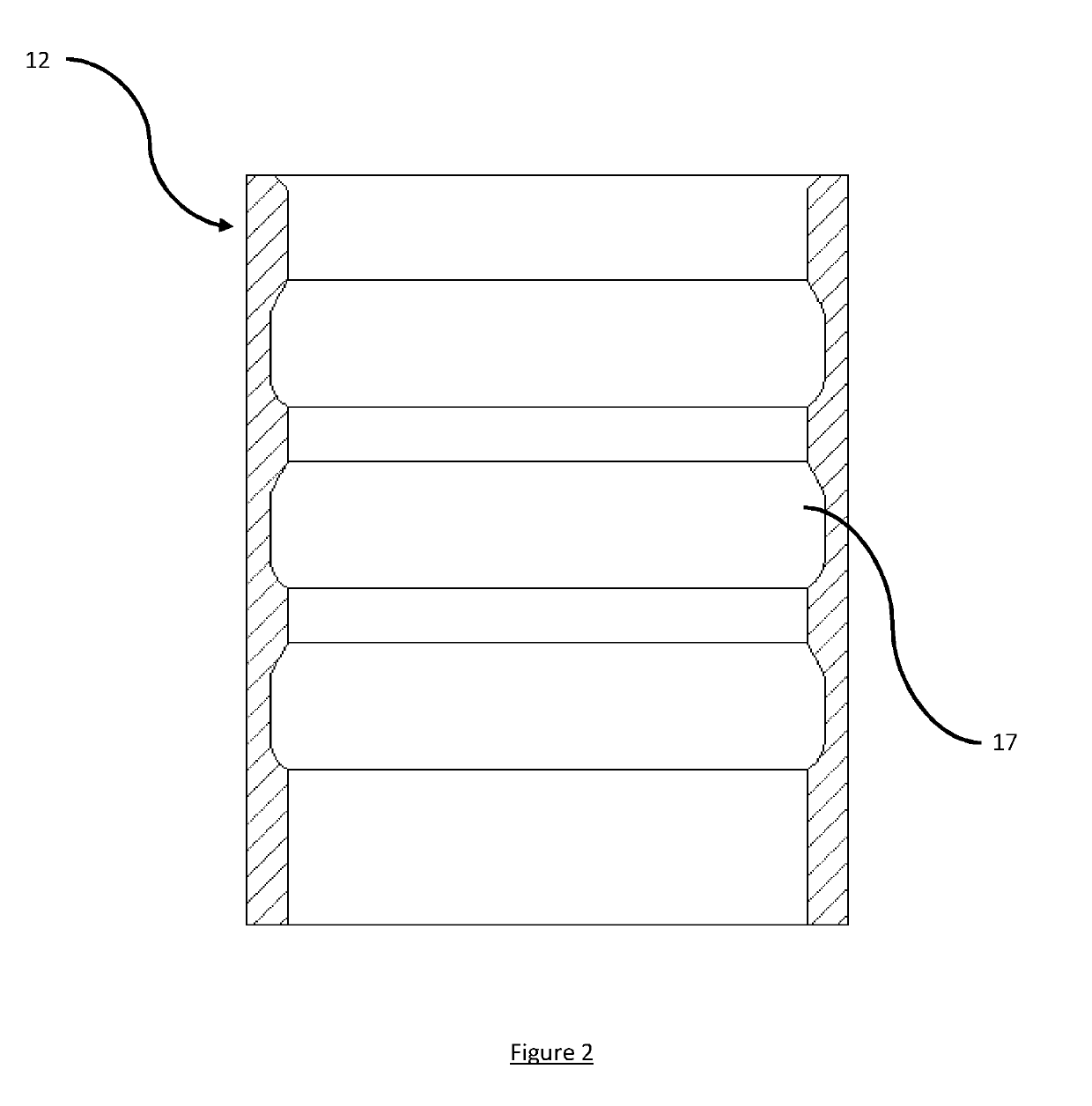
[0044]FIG. 2 is a cross-sectional view of a receptacle;

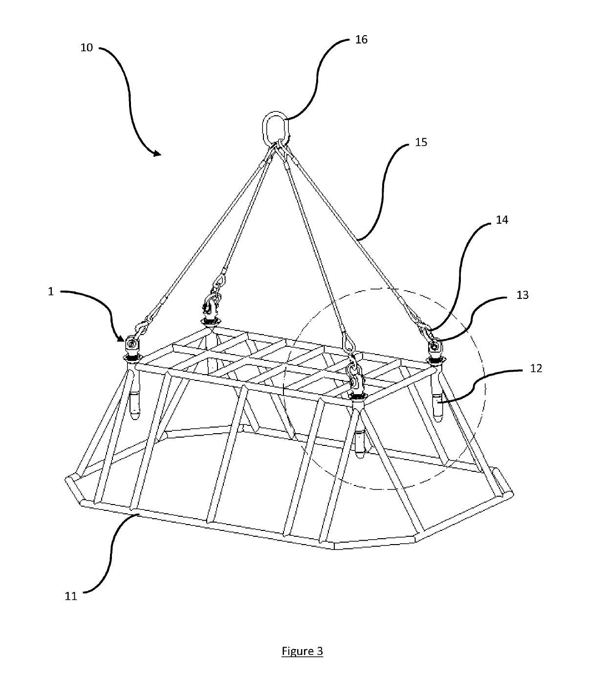
[0045]FIG. 3 is a perspective view of an assembly comprising four connectors rotatably mounted to a structure, with the connectors oriented in a first lifting configuration;

[0046]FIG. 4 is an enlarged view of part of the circled portion in FIG. 3;

[0047]FIG. 5A is a side view of the assembly shown in FIG. 3;

[0048]FIG. 5B is a plan view of the assembly shown in FIG. 5A;

[0049]FIG. 5C is an enlarged view of the circled portion in FIG. 5B;

[0050]FIG. 6A is a side view of an assembly comprising four connectors rotatably mounted to a structure, with the connectors oriented in a second lifting configuration;

[0051]FIG. 6B is a plan view of the assembly shown in FIG. 6A;

[0052]FIG. 6C is an enlarged view of t...


PUM


Abstract

A lifting assembly (10) having a structure (11) with three or more receptacles and a two or more connectors (1). The structure comprises one or more receptacles (12). Each receptacle comprises one or more circumferential grooves (17) in its inside surface. The connector comprises a male element (4) for insertion into a receptacle, an attachment point (2), and one or more locking elements (6) provided on the outside surface of the male element for engaging with the or each groove in the inside surface of the or each receptacle so as to rotatably mount the attachment point relative to the structure. The connectors may be rotationally positioned within the receptacles to permit different lifting configurations to be used.

Description

TECHNICAL FIELD OF THE INVENTION[0001]The present invention relates to a lifting assembly comprising a structure with three or more receptacles for receiving a connector provided with an attachment point and to a method of lifting using such an assembly.BACKGROUND TO THE INVENTION[0002]Structures such as lifting frames or cages and subsea modules are conventionally provided with a plurality of attachment points to which lifting lines or cables are connected in order to lift or lower the structure using a crane or a hoist. A pad eye is an attachment point that comprises a flat base connected to a U-shaped or circular loop that forms an aperture to which a part such as a hook, a shackle or a D-ring may be connected. The part connected to the padeye may then be attached to a lifting line.[0003]Each padeye has a fixed orientation relative to the structure so that, in use, it remains in alignment with the connected lifting line when the structure is lifted and is thus not subject to an a...

Claims


Application Information

Patent Timeline
IPC IPC(8): B66C1/66
CPCB66C1/66
Inventor JACKSON, JONATHANTEIXEIRA, MARCO
Owner BALLTEC
Why Eureka
Try Eureka