Rotary cylinder type compressor
a compressor and cylinder technology, applied in the direction of machines/engines, rotary/oscillating piston pump components, liquid fuel engines, etc., can solve the problems of increased compression loss and deterioration of compression performan
- Summary
- Abstract
- Description
- Claims
- Application Information
AI Technical Summary
Benefits of technology
Problems solved by technology
Method used
Image
Examples
first embodiment
(Modification of First Embodiment)
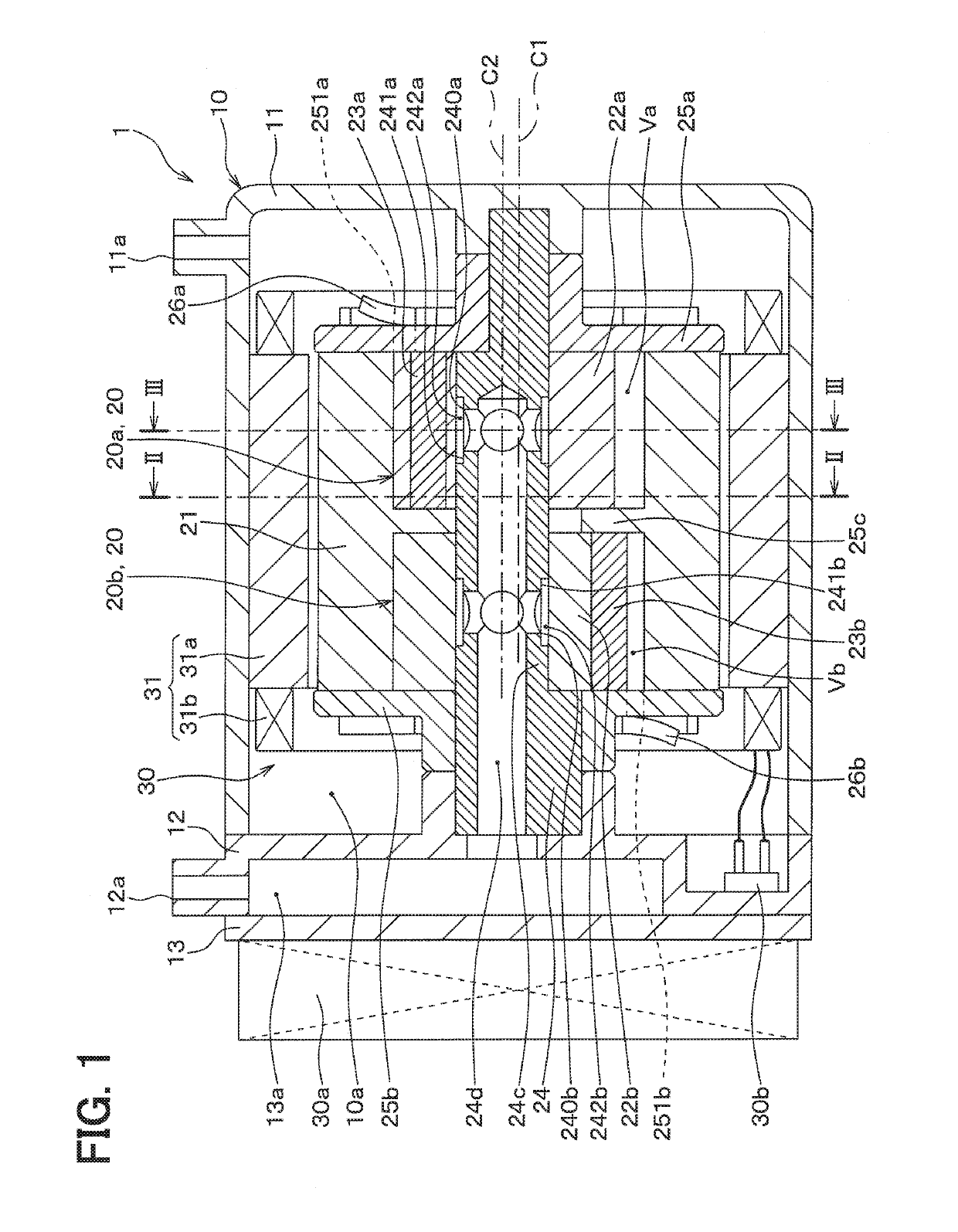
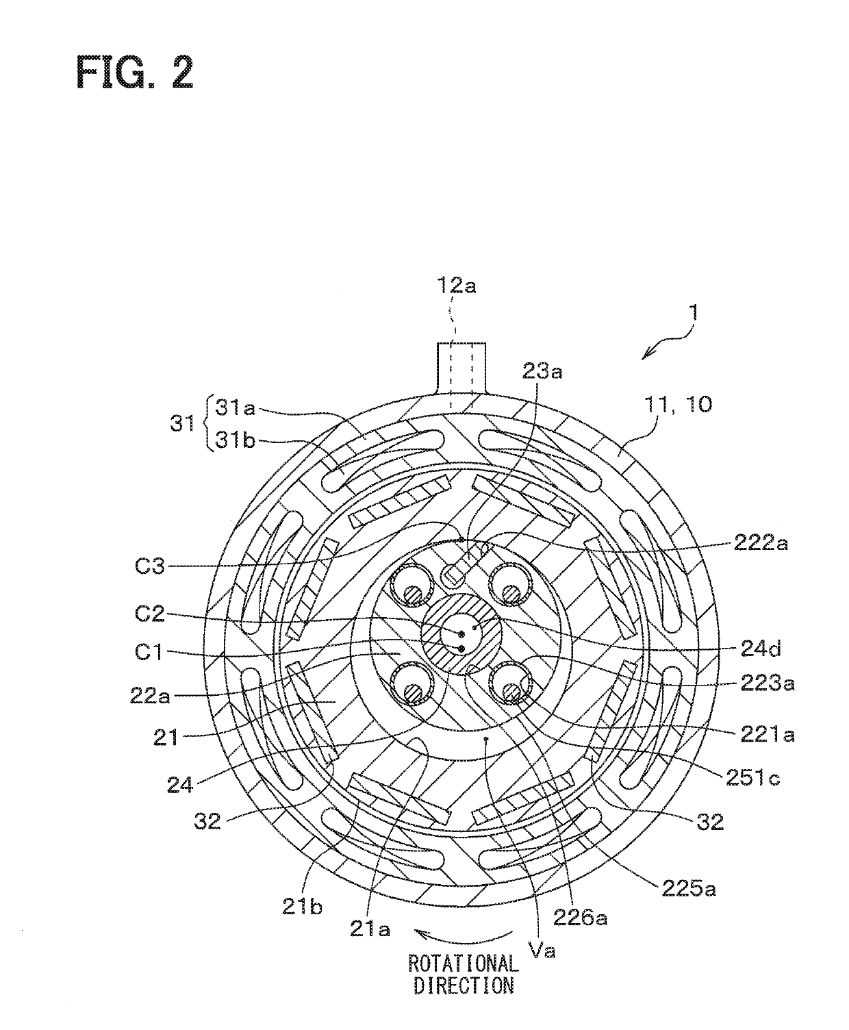
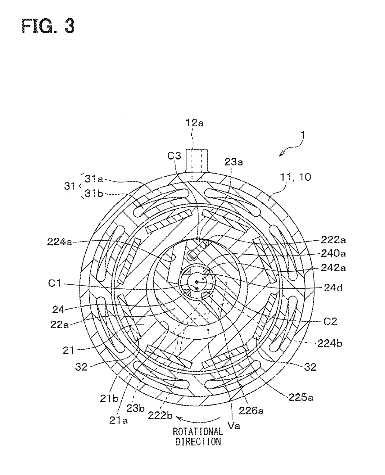
[0164]The first embodiment exemplifies the structure, in which each rotor 22a, 22b and the cylinder 21 contact with each other at the adjoining portion C3 at the rotational angle θ, at which the refrigerant pressure of the corresponding compression space Va_OUT, Vb_OUT reaches the discharge pressure. However, the present disclosure should not be limited to this structure.
[0165]For example, the compressor 1 may be configured such that each rotor 22a, 22b and the cylinder 21 do not contact with each other at the rotational angle θ, at which the refrigerant pressure of the corresponding compression space Va_OUT, Vb_OUT reaches the discharge pressure.
[0166]FIG. 10 is an axial cross-sectional view of the compression mechanism 20 of this modification. FIG. 10 corresponds to FIG. 8 of the first embodiment and shows the axial cross section of the primary compression mechanism portion 20a at the rotational angle θ, at which the refrigerant pressure of the pr...
second embodiment
(Modification of Second Embodiment)
[0189]The second embodiment exemplifies the structure, in which each rotor 22a, 22b and the cylinder 21 contact with each other at the adjoining portion C3 at the rotational angle θ, at which the refrigerant pressure of the corresponding compression space Va_OUT, Vb_OUT reaches the discharge pressure. However, the present disclosure should not be limited to this structure.
[0190]For example, as shown in FIG. 14, the compressor 1 may be configured such that each rotor 22a, 22b and the cylinder 21 do not contact with each other at the rotational angle θ, at which the refrigerant pressure of the primary compression space Va_OUT reaches the discharge pressure. FIG. 14 corresponds to FIG. 13 of the second embodiment and shows the axial cross section of the primary compression mechanism portion 20a at the rotational angle θ, at which the refrigerant pressure of the primary compression space Va_OUT reaches the discharge pressure.
Third Embodiment
[0191]Next,...
third embodiment
(Modification of Third Embodiment)
[0208]The third embodiment exemplifies the structure, in which each rotor 22a, 22b and the cylinder 21 contact with each other at the adjoining portion C3 at the rotational angle θ, at which the refrigerant pressure of the corresponding compression space Va_OUT, Vb_OUT reaches the discharge pressure. However, the present disclosure should not be limited to this structure.
[0209]For example, the compressor 1 may be configured such that each rotor 22a, 22b and the cylinder 21 do not contact with each other at the rotational angle θ, at which the refrigerant pressure of the corresponding compression space Va_OUT, Vb_OUT reaches the discharge pressure.
[0210]FIG. 19 is an axial cross-sectional view of the compression mechanism 20 of this modification. FIG. 19 corresponds to FIG. 17 of the third embodiment and shows the axial cross section of the primary compression mechanism portion 20a at the rotational angle θ, at which the refrigerant pressure of the p...
PUM
 Abstract
Description
Claims
Application Information
 - R&D
- Intellectual Property
- Life Sciences
- Materials
- Tech Scout
- Unparalleled Data Quality
- Higher Quality Content
- 60% Fewer Hallucinations
Browse by: Latest US Patents, China's latest patents, Technical Efficacy Thesaurus, Application Domain, Technology Topic, Popular Technical Reports.
© 2025 PatSnap. All rights reserved.Legal|Privacy policy|Modern Slavery Act Transparency Statement|Sitemap|About US| Contact US: help@patsnap.com


