Vehicle-integrated lidar system

a lidar system and vehicle technology, applied in the field of vehicle-integrated lidar systems, can solve the problems of poor angular resolution and insufficient measurement spacing (i.e. angular resolution) to identify the detailed boundaries of objects

Active Publication Date: 2019-07-04
OKEEFFE JAMES THOMAS
View PDF3 Cites 50 Cited by
  • Summary
  • Abstract
  • Description
  • Claims
  • Application Information

AI Technical Summary

Benefits of technology

[0017]Instead of generating a uniform laser pulse density throughout the FOV, the disclosed techniques provide for non-uniform laser pulse density by dynamically steering a laser based on data indicating the location of important features in the FOV (e.g. boundaries of an object, a person recognized in a digital image). This data-driven non-uniform laser pulse spacing has the further benefit of further localizing the important features. In another advantage the boundaries of objects in the FOV can be progressively localized by refining laser steering parameters in regions of the FOV.
[0018]In another advantage the laser pulse density can be selected in various parts of the FOV (e.g. left side, right side, or between −20 degrees and −30 degrees) based on aspects of the location of the laser range finder (e.g. the terrain, the GPS location, the time of day or a classification for the type of location such as urban or rural).
[0019]In a related advantage the disclosed techniques allow laser steering parameters to encode for a wide variety of predefined high-density laser pulse patterns. Upon instructing or configuring a steerable laser with such laser steering parameters, the steerable laser can generate the corresponding non-uniform pulse density region in the FOV. For example, a vehicle of model A with a dynamically steered laser range finder can develop and share a library of laser point patterns effective to test the hypothesis that a vehicle of model B is in the FOV. Using the one of more of the disclosed methods a vehicle of model A could estimate that a vehicle of model B is present in the FOV, access a database of laser steering parameters designed to test the hypothesis that the vehicle in the FOV is of model B and configure a dynamically steerable laser to generate a non-uniform laser pulse sequence to best test the hypothesis that the vehicle is model B. Therefore the disclosed techniques enable customized laser pulse patterns to be generated, shared and used to guide a steerable laser range finder. The laser pulse patterns can be customized to the geometry of vehicle model A and placement of the dynamically steered laser range finder. A dynamically steered range finder could be preprogrammed with a library of laser pulse patterns corresponding to the vehicle it is mounted on and placement on the vehicle.

Problems solved by technology

Hence a LIDAR that scans a field of view (FOV) in a uniform deterministic manner can provide poor angular resolution.
This measurement spacing (i.e. angular resolution) can be insufficient for identifying the detailed boundaries of objects.
U.S. Pat. No. 9,383,753 further assumes a rotating LIDAR and does not provide for arbitrary laser orientation within a scan.
Hence, dynamically adapting LIDAR measurement density within a scan, to improve the accuracy of object boundary detection in the FOV remains a challenge.

Method used


Image

  • Vehicle-integrated lidar system
  • Vehicle-integrated lidar system
  • Vehicle-integrated lidar system

Examples


Embodiment Construction

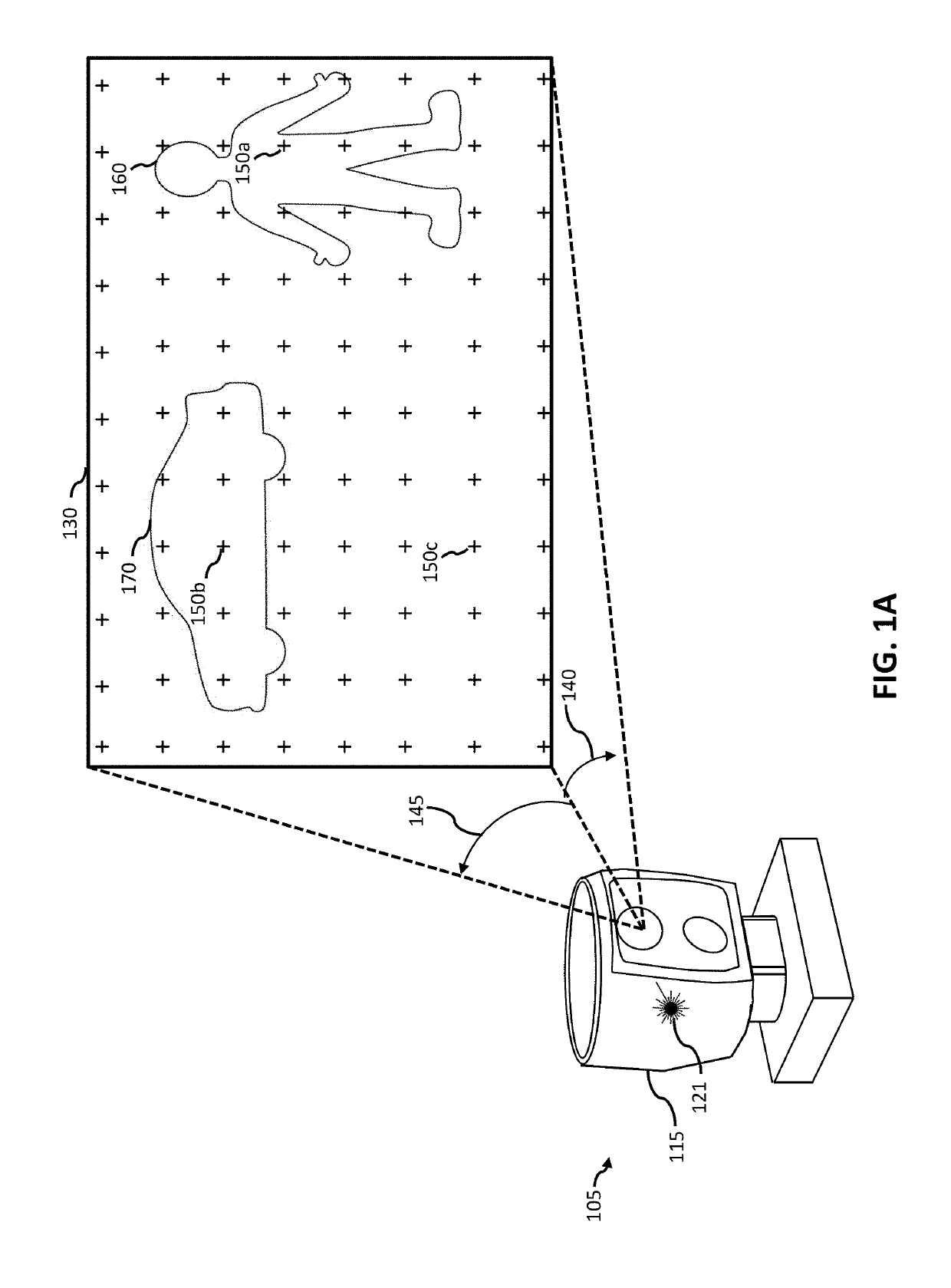
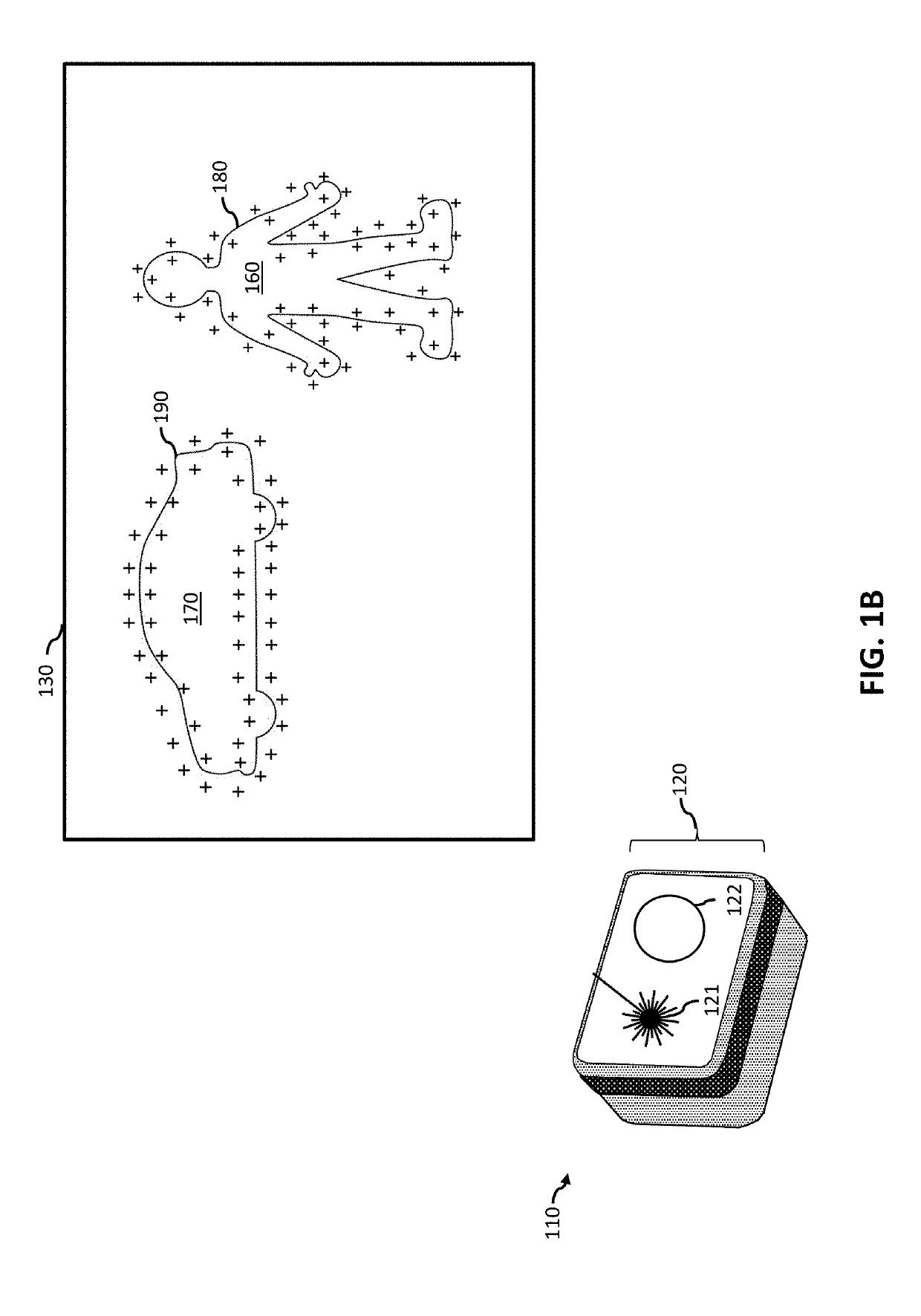
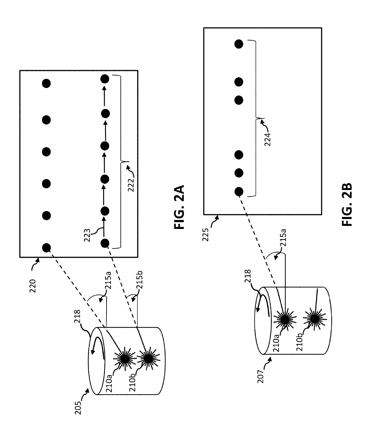
[0080]In digital photography light from is received at a sensor form many points in the local environment at once. In contrast, a laser range finder can use a relatively small number of lasers (e.g. 1-64) to generate laser pulses aimed sequentially at a number of points (e.g. 100,000) to perform laser ranging scans of the FOV. Hence, the laser pulses (e.g. and corresponding time of flight measurements in discrete directions) represent a scarce resource and the FOV is often undersampled with respect to sensing detailed boundaries of objects in the local environment. Many LIDARs mechanically rotate with a constant or nearly constant angular velocity. Such rotating LIDARs can sweep one or more lasers through a deterministic range of directions (e.g. each laser sweeping through a 360 degree azimuthal range at a fixed elevation angle). This type of operation does not constitute dynamically steering the laser(s) in a LIDAR. The angular momentum of the spinning portion in a mechanical LIDA...


PUM


Abstract

Mounting a LIDAR above or external to a vehicle can enhance the LIDAR field of view but can conflict with vehicle aesthetics and ergonomics. Within embodiments, vehicle-integrated systems for distributing laser beams around a vehicle to increase coverage with a low-profile laser range finder are disclosed. A LIDAR can be embedded beneath a roof or body panel of a vehicle as part of a laser distribution system including a set of reflectors and lenses operable to adapt the LIDAR field of view to the vehicle shape. The set of embedded reflectors can guide laser beams parallel (e.g. within the roof structure), to and from the set of lenses at the roof edge to transmit the guided laser into regions of the surrounding beyond the direct field of view of the LIDAR. In other embodiments a beam guide (e.g. including a headlight assembly) can enable a LIDAR to perform ranging from behind a vehicle body panel.

Description

CROSS-REFERENCE TO RELATED APPLICATIONS[0001]This application is a continuation in part of International Application No. PCT / US17 / 32585, filed May 15, 2017, which claims the benefit of priority to each of: U.S. provisional patent application Ser. No. 62 / 337,867, filed on May 18, 2016; U.S. provisional patent application Ser. No. 62 / 350,670, filed on Jun. 15, 2016; U.S. provisional patent application Ser. No. 62 / 441,492, filed on Jan. 2, 2017; and U.S. provisional patent application Ser. No. 62 / 441,563, filed on Jan. 3, 2017.BACKGROUND[0002]In digital photography a charge-coupled-device CCD sensor can gather light from several million local directions simultaneously to generate detailed images. In contrast, most laser range finders, such as a light detection and ranging system (LIDAR) scan or rotate laser beams and measure the time of flight (TOF) in much smaller number of directions. This sequential measurement approach limits the total number of range measurements per second. Hence...

Claims


Application Information

Patent Timeline
Patent Type & Authority Applications(United States)
IPC IPC(8): G01S7/481G01S17/93G01S17/42G01S17/89G01S17/931
CPCG01S7/4817G01S17/936G01S17/42G01S7/4818G01S17/89G01S7/4814G01S7/4816G01S17/931
Inventor O'KEEFFE, JAMES THOMAS
Owner OKEEFFE JAMES THOMAS
Why Eureka
Try Eureka