Connector assembly with retractable probe contact recessed behind mating surface and stationary pad contact extending beyond mating surface

a technology of electrical connectors and probes, applied in the direction of coupling contact members, coupling device connections, coupling parts, etc., can solve the problems of compromising the appearance of even and smooth configuration, and achieve the effect of efficient wireless transmission

Active Publication Date: 2019-07-04
FUDING PRECISION IND ZHENGZHOU CO LTD +1
View PDF0 Cites 0 Cited by
  • Summary
  • Abstract
  • Description
  • Claims
  • Application Information

AI Technical Summary

Benefits of technology

[0005]To achieve the above-mentioned object, an electrical connector assembly includes a receptacle connector and the plug connector mated with each other. The receptacle connector includes a first shell, a first magnetic section surrounding the first shell, and a first wireless module retained in the first shell. The first shell defines a first mating surface. The first wireless module is hidden behind the first mating surface while the first magnetic section is exposed upon the first mating surface. The plug connector includes a second shell, a second magnetic section surrounding the second shell, and a second wireless module retained in the second shell. The second wireless module is hidden behind the second mating surface while the second magnetic section is exposed upon the second mating surface. The receptacle connector further includes a plurality of retractable probe contacts each having a first contacting section exposed upon the first mating surface. The plug connector further includes a plurality of stationary pad contacts each having a second contacting section exposed and extending beyond the second mating surface. During mating, the first mating surface and the second mating surface intimately confront each other in the mating direction by the corresponding magnetic forces so as to have the second contacting section push the first contacting section backward to form a space behind the first mating surface to receive the second contacting section therein, thus achieving precise alignment between the first mating section and the second mating section and assuring alignment between the first wireless module and the second wireless module in the mating direction for efficient wireless transmission.

Problems solved by technology

In addition, the traditional alignment structure formed by the housing of the connector may include corresponding protruding structures and / or the recessed structures, thus jeopardizing the even and smooth configuration on an appearance thereof.

Method used


Image

  • Connector assembly with retractable probe contact recessed behind mating surface and stationary pad contact extending beyond mating surface
  • Connector assembly with retractable probe contact recessed behind mating surface and stationary pad contact extending beyond mating surface
  • Connector assembly with retractable probe contact recessed behind mating surface and stationary pad contact extending beyond mating surface

Examples


Embodiment Construction

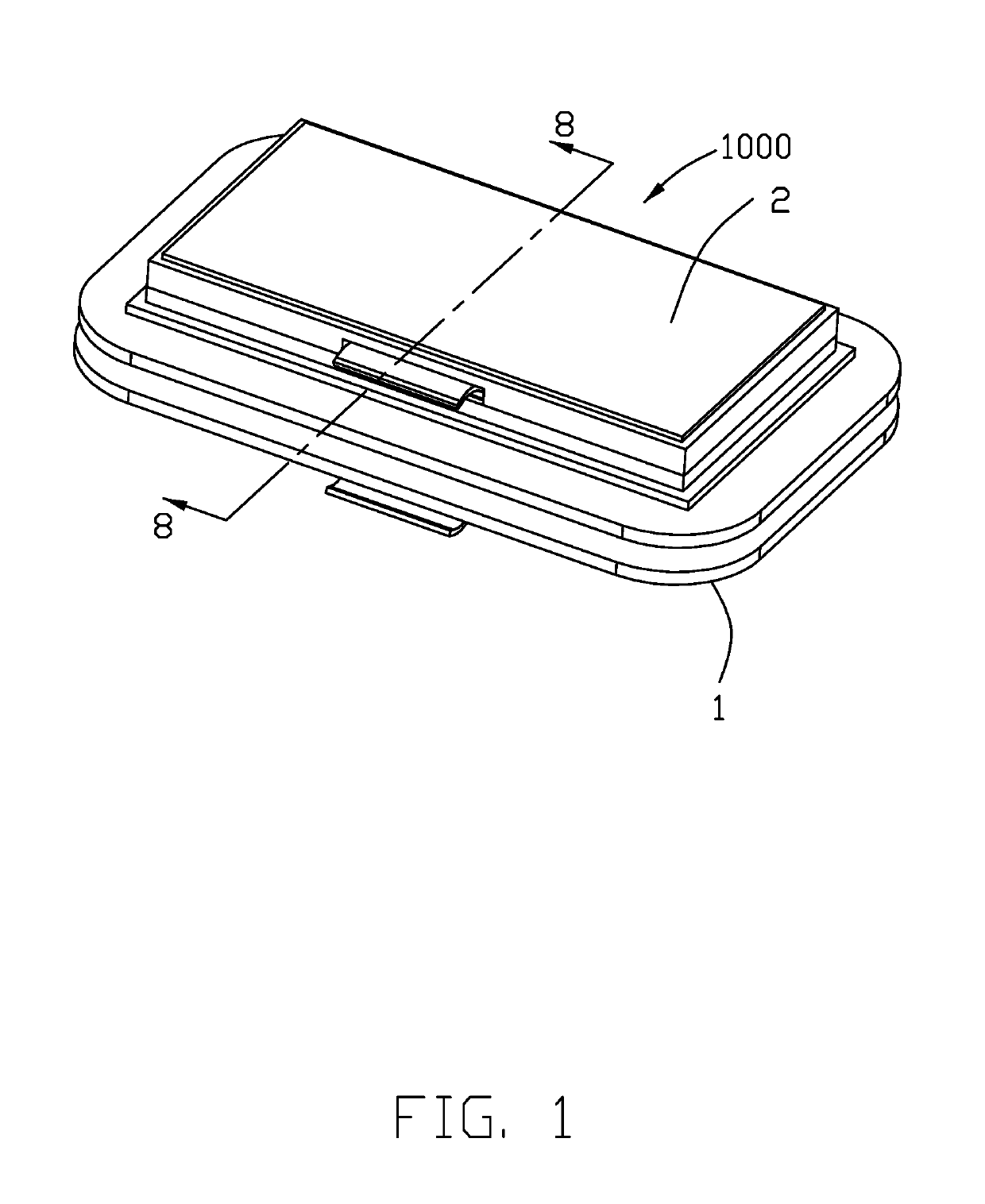
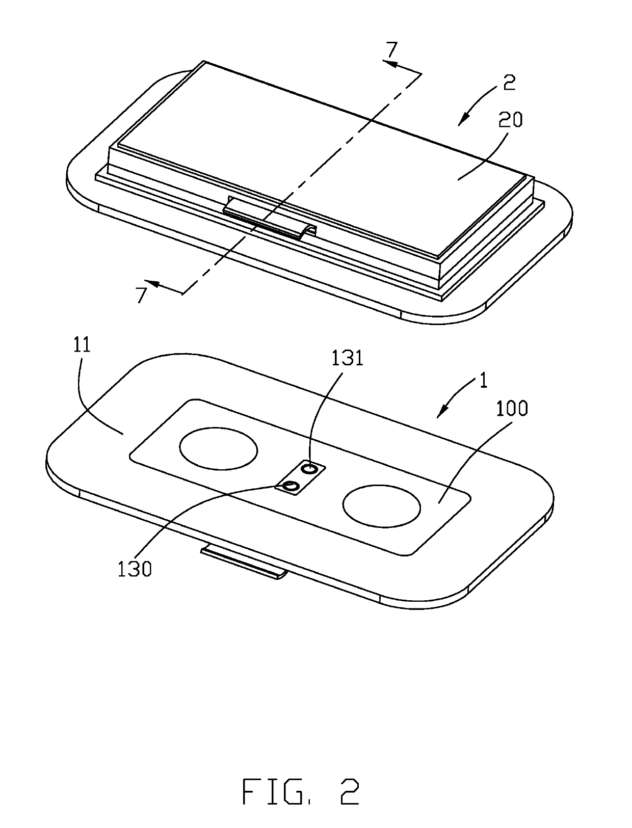
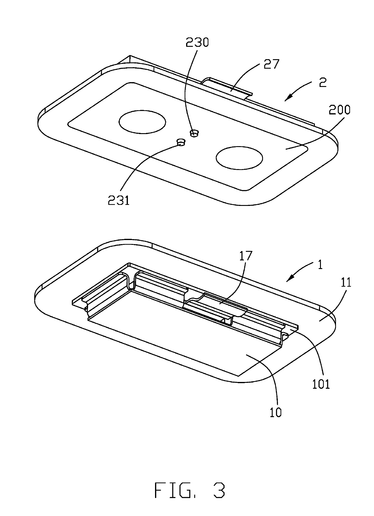
[0014]Referring to FIGS. 1 to 8, an electrical connector assembly 1000 includes a first / receptacle connector 1 and a second / plug connector 2 mated with each other. The first connector 1 is used with the portable device (not shown) and the second connector 2 is used with the peripheral (not shown) for achieving communication therebetween.

[0015]The first connector 1 includes a first shell 10, the first magnetic section 11 surrounding the first shell, and a pair of first wireless modules 12 retained in the first shell 10. The first shell 10 forms a first mating surface 100 and the first wireless modules 12 are hidden behind the first mating surface 100. The first magnetic section 11 is coplanar with the first mating surface 100. The second connector 2 includes a second shell 20, the second magnetic section 21 surrounding the first shell 20, and a pair of second wireless modules 22. The second shell 20 forms a second mating surface 200 and the second wireless modules 22 are hidden behin...


PUM


Abstract

An electrical connector assembly comprising a first connector and a second connector mated with each other. The first connector includes a first shell forming a first mating surface thereon. A retractable first contact has a first contacting section moveable between an outer position coplanar with the first mating surface and an inner position recessed from the first mating surface. The second connector includes a second shell forming a second mating surface thereon. A stationary second contact has a second contacting section protruding beyond the second mating surface. During mating, the second contacting section abuts against the first contacting section in the mating direction and protrudes beyond the first mating surface to be snugly received within the first connector.

Description

BACKGROUND OF THE INVENTION1. Field of the Invention[0001]The present invention relates generally to an electrical connector assembly, and more particularly to the electrical connector assembly having mated plug connector and receptacle connector by magnetic forces with reliable alignment therebetween.2. Description of Related Arts[0002]U.S. Pat. No. 9,385,471 discloses the connector assembly having a first connector with a retractable probe contact originally extending beyond the corresponding mating surface and a second connector with a stationary pad contact constantly coplanar with the corresponding mating surface wherein the first connector and the second connector are mated with each other via magnetic forces. Anyhow, the alignment between the first connector and the second connector along the mating direction is essentially made by the peripheral structures of the housing rather than the intimately mated probe contact and pad contact. In addition, the traditional alignment st...

Claims


Application Information

Patent Timeline
Patent Type & Authority Applications(United States)
IPC IPC(8): H01R12/71H01R13/24H01R13/62
CPCH01R12/716H01R13/2471H01R13/6205H01R13/2407H04B3/02H01R13/2421
Inventor HSU, SHUO-HSIULIN, NAN-HUNGSZU, MING-LUN
Owner FUDING PRECISION IND ZHENGZHOU CO LTD
Why Eureka
Try Eureka