Receiving end of cross-wound multi-phase flat magnetic core of bridge arm applied to wireless power supply of electric vehicles

A flat magnetic core, wireless power supply technology, applied in the direction of transformer/inductor coil/winding/connection, transformer/inductor core, circuit, etc., can solve the problem of poor power supply efficiency, achieve good magnetic field shielding effect, lateral Strong offset capability, guaranteed power and efficiency

Active Publication Date: 2017-07-21
HARBIN INST OF TECH
View PDF5 Cites 0 Cited by
  • Summary
  • Abstract
  • Description
  • Claims
  • Application Information

AI Technical Summary

Problems solved by technology

[0004] The purpose of the present invention is to improve the problem of poor power supply efficiency caused by the structure of the ferrite core of the power supply track in the wireless power supply of electric vehicles, and provides a bridge arm cross-wound multi-phase flat magnetic core receiver for wireless power supply of electric vehicles. end

Method used


Image

  • Receiving end of cross-wound multi-phase flat magnetic core of bridge arm applied to wireless power supply of electric vehicles
  • Receiving end of cross-wound multi-phase flat magnetic core of bridge arm applied to wireless power supply of electric vehicles
  • Receiving end of cross-wound multi-phase flat magnetic core of bridge arm applied to wireless power supply of electric vehicles

Examples


specific Embodiment approach 1

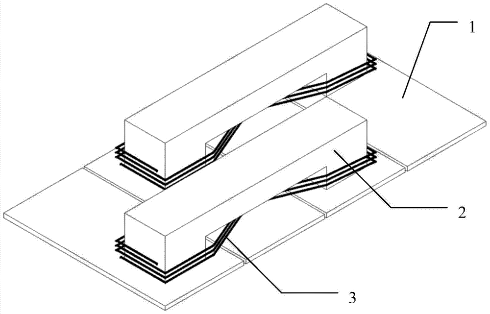
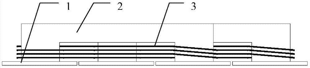
[0028] Specific implementation mode one: the following combination Figure 1 to Figure 15 This embodiment is described. The receiving end of the cross-wound multi-phase flat magnetic core of the bridge arm applied to the wireless power supply of electric vehicles described in this embodiment is adapted to the bipolar wireless transmitting guide rail of the wireless energy transmitting end. The magnetic field directions of adjacent magnetic poles are opposite; the receiving end of the magnetic core includes m×n planar magnetic cores 1, n bridge arm magnetic cores 2 and n receiving coils 3, and m and n are both integers greater than 1;

[0029] m×n planar magnetic cores 1 are placed in parallel and equally spaced in sequence, and the first bridge arm magnetic core 2 is sequentially connected to the first planar magnetic core 1, the n+1th planar magnetic core 1, and the 2n+1th block between the planar magnetic core 1,..., and the (m-1)×n+1th planar magnetic core 1; the second bri...

specific Embodiment approach 2

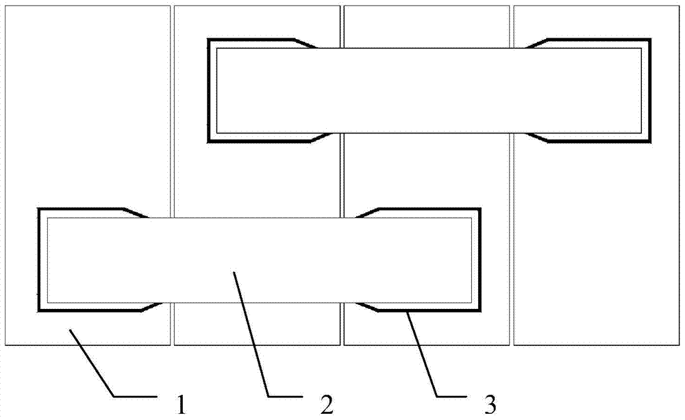
[0033] Specific implementation mode two: the following combination Figure 1 to Figure 13 This embodiment will be described, and this embodiment will further describe Embodiment 1. The m ends of each bridge arm magnetic core 2 are respectively connected to the center of the corresponding planar magnetic core 1 .

specific Embodiment approach 3

[0034] Specific implementation mode three: the following combination figure 1 , Figure 5 , Figure 9 and Figure 13 Describe this embodiment mode, this embodiment mode will further illustrate Embodiment 1 or 2. The bridge arm magnetic core 2 is composed of m vertical segments and a horizontal segment, and m vertical segments and a horizontal segment are connected in sequence. m-1 rectangular frames together; or the bridge arm magnetic core 2 is m-1 arc-shaped frames sequentially connected together.

[0035] When the bridge arm magnetic core 2 is a rectangular frame with m−1 connections, the receiving coil 3 is cross-wound on its m vertical sections.


PUM


Abstract

A bridge arm cross winding type multiphase flat-plate magnetic core receiving end for wireless power supply to electric vehicles belongs to the technical field of wireless power transmission. The invention aims to solve the problem that the efficiency of power supply is low due to the structure of a power supply rail ferrite magnetic core in wireless power supply to electric vehicles. The receiving end comprises m*n flat-plate magnetic cores, n bridge arc magnetic cores, and n receiving coils. The m*n flat-plate magnetic cores are sequentially placed in parallel and at equal intervals. The first bridge arc magnetic core is connected across the first flat-plate magnetic core, the (n+1)th flat-plate magnetic core,..., and the ((m-1)*n+1)th flat-plate magnetic core in sequence. The nth bridge arc magnetic core is connected across the nth flat-plate magnetic core, the (2n)th flat-plate magnetic core,..., and the (m*n)th flat-plate magnetic core in sequence. The n bridge arc magnetic cores are sequentially arranged in parallel on the flat-plate magnetic cores. Each bridge arc magnetic core is connected across the m tail ends of the corresponding m flat-plate magnetic cores and is wound with a receiving coil, and the receiving coil is sequentially wound at the m tail ends in a cross manner. The bridge arm cross winding type multiphase flat-plate magnetic core receiving end of the invention is used as an electric energy receiving end for wireless power supply to electric vehicles.

Description

technical field [0001] The invention relates to a bridge arm cross-wound multi-phase flat magnetic core receiving end applied to wireless power supply of electric vehicles, and belongs to the technical field of wireless energy transmission. Background technique [0002] At present, there are two major bottlenecks in the development of electric vehicles. One is the battery on the vehicle. From the perspective of recent technology, there are many problems such as volume, weight, price, material, safety, charging speed, and lifespan. In addition, the production of batteries The process is a process of high pollution, resource consumption, and damage to the ecological environment. These characteristics bring difficulties to the industrialization of electric vehicles; the second is the problem of charging infrastructure on the ground. On the one hand, due to the long charging time, a large amount of charging or replacement is required. Electric facilities bring great difficulties...

Claims


Application Information

Patent Timeline
Patent Type & Authority Patents(China)
IPC IPC(8): H02J50/10H02J50/70H01F27/26H01F27/30H01F38/14
Inventor 朱春波魏国姜金海汪超
Owner HARBIN INST OF TECH
Why Eureka
Try Eureka