The receiving end of the bridge arm wound flat magnetic core applied to the wireless power supply of electric vehicles

A flat magnetic core and wireless power supply technology, which is applied in the direction of transformer/inductor coil/winding/connection, transformer/inductor core, electrical components, etc., can solve the problems of poor power supply efficiency and achieve good magnetic field shielding effect and coupling High degree, good electromagnetic compatibility effect

Active Publication Date: 2018-07-06
HARBIN INST OF TECH
View PDF4 Cites 0 Cited by
  • Summary
  • Abstract
  • Description
  • Claims
  • Application Information

AI Technical Summary

Problems solved by technology

[0004] The purpose of the present invention is to improve the problem of poor power supply efficiency caused by the ferrite core structure of the power supply track in the wireless power supply of electric vehicles, and to provide a bridge arm wound flat magnetic core receiving end for wireless power supply of electric vehicles

Method used


Image

  • The receiving end of the bridge arm wound flat magnetic core applied to the wireless power supply of electric vehicles
  • The receiving end of the bridge arm wound flat magnetic core applied to the wireless power supply of electric vehicles
  • The receiving end of the bridge arm wound flat magnetic core applied to the wireless power supply of electric vehicles

Examples


specific Embodiment approach 1

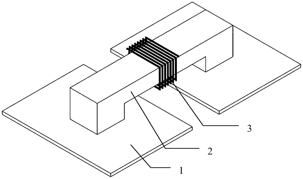
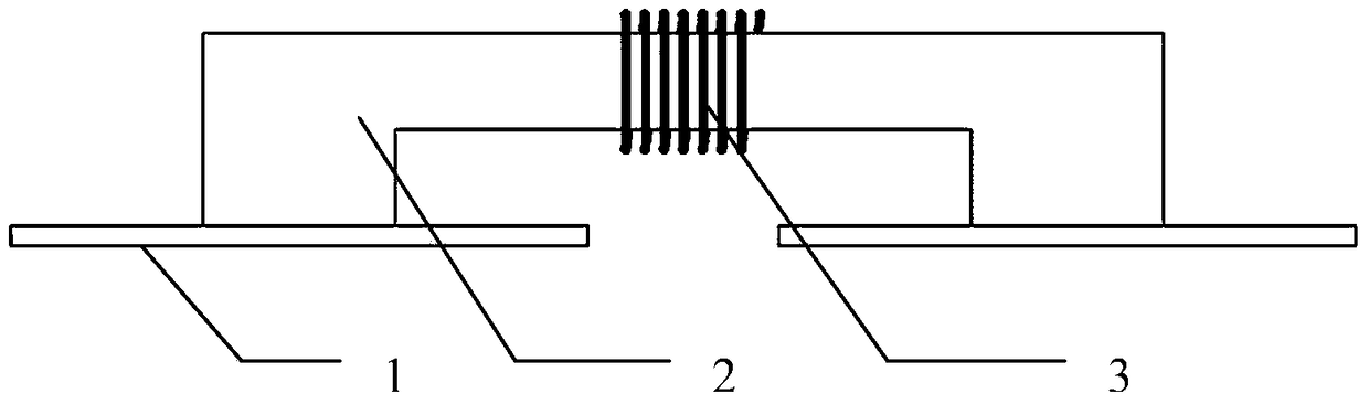
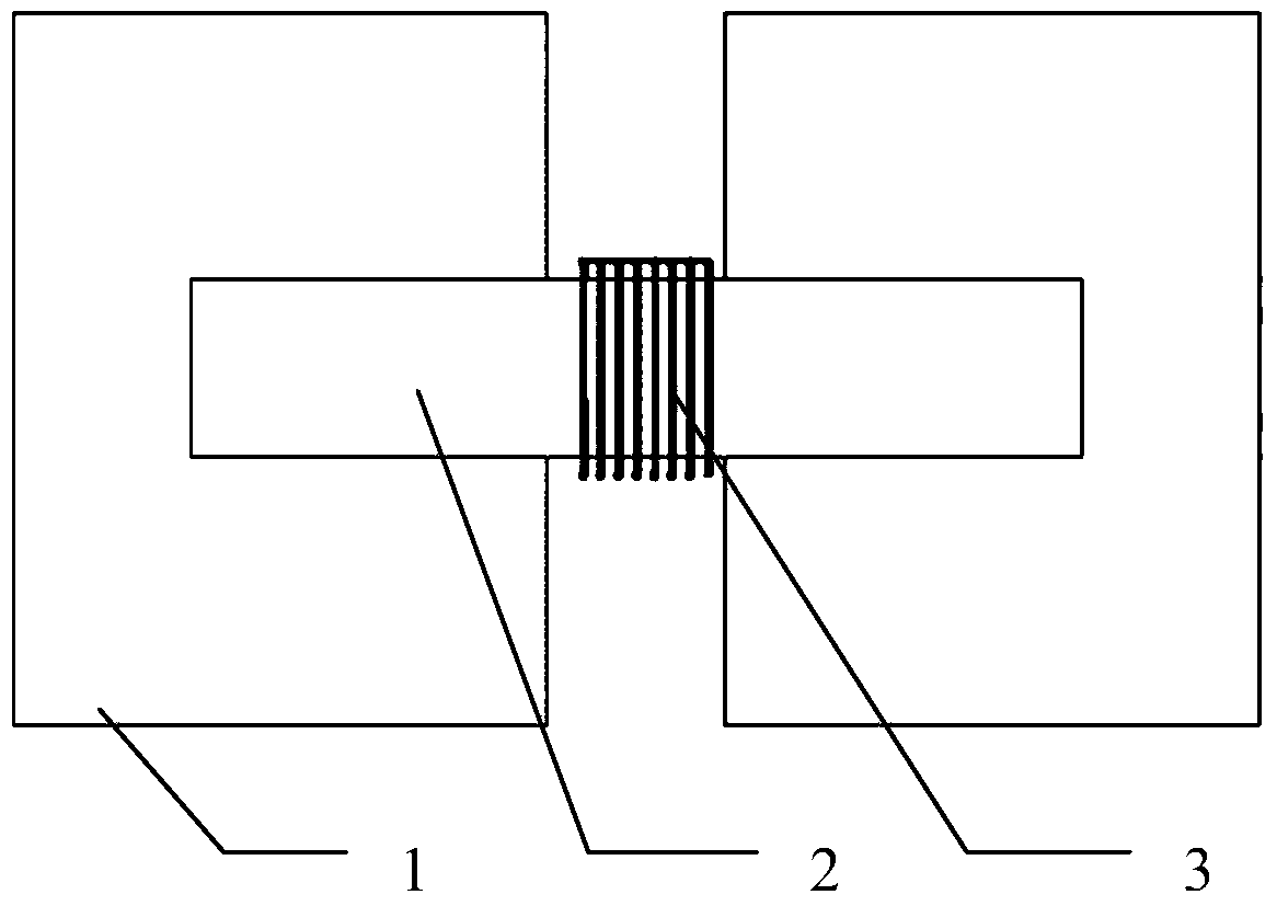
[0024] Specific implementation mode one: the following combination Figure 1 to Figure 11 This embodiment is described. The receiving end of the bridge arm wound flat magnetic core applied to the wireless power supply of electric vehicles described in this embodiment is adapted to the bipolar wireless transmitting guide rail of the wireless energy transmitting end. The adjacent magnetic pole of the transmitting guide rail The direction of the magnetic field is opposite; the receiving end of the flat magnetic core includes n flat magnetic cores 1, bridge arm magnetic cores 2 and n-1 receiving coils 3,

[0025] n planar magnetic cores 1 are arranged in parallel, and there is a gap between two adjacent planar magnetic cores 1, and bridge arm magnetic cores 2 are sequentially connected between n planar magnetic cores 1, and two adjacent planar magnetic cores 1 The receiving coil 3 is helically wound centrally on the core segments of the bridge arm magnetic core 2 .

[0026] In th...

specific Embodiment approach 2

[0028] Specific implementation mode two: the following combination Figure 1 to Figure 8 The present embodiment will be described. This embodiment will further describe the first embodiment. The n ends of the bridge arm magnetic cores 2 are respectively connected to the centers of the corresponding planar magnetic cores 1 .

specific Embodiment approach 3

[0029] Specific implementation mode three: the following combination figure 1 , figure 2 , Figure 5 and Figure 6 Describe this embodiment mode, this embodiment mode will further illustrate Embodiment 1 or 2. The bridge arm magnetic core 2 is composed of n vertical segments and a horizontal segment, and the n vertical segments and a horizontal segment are sequentially connected to each other. n-1 rectangular frames together; or the bridge arm magnetic core 2 is n-1 arc-shaped frames connected together in sequence.


PUM


Abstract

The utility model relates to a bridge arm wound flat magnetic core receiving end applied to wireless power supply of electric vehicles, belonging to the technical field of wireless power transmission. The invention aims to improve the problem of poor power supply efficiency caused by the structure of the power supply rail ferrite core in the wireless power supply of electric vehicles. It is adapted to the bipolar wireless transmitting guide rail of the wireless power transmitting end, and the magnetic field directions of the adjacent magnetic poles of the transmitting guide rail are opposite; the flat magnetic core receiving end includes n flat magnetic cores, bridge arm magnetic cores and n-1 receiving The coil, n pieces of flat magnetic cores are arranged in parallel, and there is a gap between two adjacent flat magnetic cores, the bridge arm magnetic cores are sequentially bridged between the n flat magnetic cores, and the gap between the adjacent two flat magnetic cores is The core segment of the bridge arm core is helically wound on the center of the receiving coil. The present invention is used as a power receiving terminal for wireless power supply of electric vehicles.

Description

technical field [0001] The invention relates to a bridge arm wound flat magnetic core receiving end applied to wireless power supply of electric vehicles, and belongs to the technical field of wireless energy transmission. Background technique [0002] At present, there are two major bottlenecks in the development of electric vehicles. One is the battery on the vehicle. From the perspective of recent technology, there are many problems such as volume, weight, price, material, safety, charging speed, and lifespan. In addition, the production of batteries The process is a process of high pollution, resource consumption, and damage to the ecological environment. These characteristics bring difficulties to the industrialization of electric vehicles; the second is the problem of charging infrastructure on the ground. On the one hand, due to the long charging time, a large amount of charging or replacement is required. Electric facilities bring great difficulties to municipal cons...

Claims


Application Information

Patent Timeline
Patent Type & Authority Patents(China)
IPC IPC(8): H02J50/10H01F27/30H01F27/26
Inventor 朱春波魏国姜金海汪超
Owner HARBIN INST OF TECH
Why Eureka
Try Eureka