Power supply connector assemblies

a technology of power supply connectors and connector assemblies, which is applied in the direction of coupling device connections, securing/insulating coupling contact members, two-pole connections, etc., can solve the problems that the conventional power supply connector assemblies used for electrical coupling power adapter assemblies to electric power supplies are often susceptible to breakag

Inactive Publication Date: 2019-07-04
APPLE INC
View PDF8 Cites 8 Cited by
  • Summary
  • Abstract
  • Description
  • Claims
  • Application Information

AI Technical Summary

Benefits of technology

[0005]For example, in some embodiments, an assembly may be provided for being electrically coupled to a power supply contact of a power supply and to a power adapter contact of a power adapter. The assembly may include an outer case defining an interior space, wherein the outer case may include a top wall, a bottom wall, a left wall, a right wall, a front wall, and an open end. The assembly may also include a power supply connector including a power supply connector contact including a power supply contact portion operative to be electrically coupled to the power supply contact of the power supply, and a power adapter connector contact portion positioned within the interior space. The assembly may also include a power adapter connector including a power adapter connector body defining a contact passageway and operative to be held with respect to the outer case, wherein, when the power adapter connector body is held with respect to the outer case, a portion of the power adapter connector body may be positioned within the open end of the outer case, and a power adapter connector contact at least partially positioned within the contact passageway and including a power adapter contact portion operative to be electrically coupled to the power adapter contact of the power adapter, and a power supply connector contact portion, wherein, when the power adapter connector body is held with respect to the outer case, the power supply connector contact portion may be electrically coupled to the power adapter connector contact portion within the interior space.
[0006]As another example, in some embodiments, an assembly may be provided for being electrically coupled to a power supply contact of a power supply and to a power adapter contact of a power adapter. The assembly may include an outer case defining an interior space. The assembly may also include a power supply connector including a power supply connector contact including a power supply contact portion operative to be electrically coupled to the power supply contact of the power supply, and a power adapter connector contact portion positioned within the interior space. The assembly may also include a power adapter connector including a power adapter connector body defining a contact passageway and operative to be held with respect to the outer case, and a power adapter connector contact at least partially positioned within the contact passageway and including a power adapter contact portion operative to be electrically coupled to the power adapter contact of the power adapter, and a power supply connector contact portion, wherein, when the power adapter connector body is held with respect to the outer case, the power supply connector contact portion may be electrically coupled to the power adapter connector contact portion within the interior space, structure within the interior space may define at least a portion of a recess guide extending between a first recess guide end and a second recess guide end within the interior space, the power adapter connector contact portion may be positioned within the interior space adjacent the second recess guide end of the recess guide, and the recess guide may be operative to prevent a user of the assembly from directly contacting the power adapter connector contact portion of the power supply connector contact positioned within the interior space.
[0007]As yet another example, in some embodiments, an assembly may be provided for being electrically coupled to a power supply contact of a power supply and to a power adapter contact of a power adapter. The assembly may include an outer case defining an interior space. The assembly may also include a power supply connector including a power supply connector contact that may include a power supply contact portion operative to be electrically coupled to the power supply contact of the power supply and a power adapter connector contact portion positioned within the interior space. The assembly may also include a power adapter connector including a power adapter connector body that may define a contact passageway, include a contact retention feature external to the contact passageway, and be operative to be held with respect to the outer case, and a power adapter connector contact at least partially positioned within the contact passageway and including a power adapter contact portion operative to be electrically coupled to the power adapter contact of the power adapter, a power supply connector contact portion that is electrically coupled to the power adapter connector contact portion within the interior space when the power adapter connector body is held with respect to the outer case, and a power adapter connector contact body held by the contact retention feature for maintain the position of the power adapter connector contact at least partially within the contact passageway when the power adapter connector body is pulled away from the interior space while the power supply connector contact portion is electrically coupled to the power adapter connector contact portion within the interior space.
[0008]This Summary is provided only to summarize some example embodiments, so as to provide a basic understanding of some aspects of the subject matter described in this document. Accordingly, it will be appreciated that the features described in this Summary are only examples and should not be construed to narrow the scope or spirit of the subject matter described herein in any way. Unless otherwise stated, features described in the context of one example may be combined or used with features described in the context of one or more other examples. Other features, aspects, and advantages of the subject matter described herein will become apparent from the following Detailed Description, Figures, and Claims.

Problems solved by technology

Conventional power supply connector assemblies used for electrically coupling power adapter assemblies to electric power supplies are often susceptible to break events that expose live electrical contacts.

Method used


Image

  • Power supply connector assemblies
  • Power supply connector assemblies
  • Power supply connector assemblies

Examples


Embodiment Construction

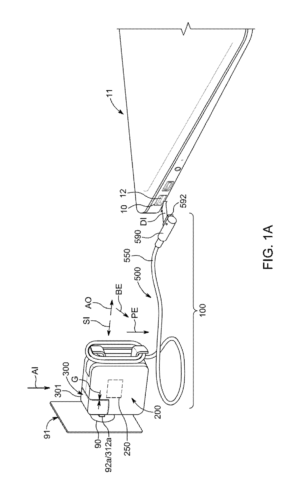
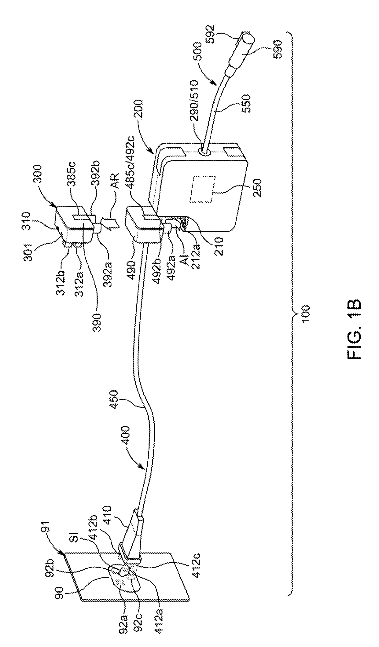
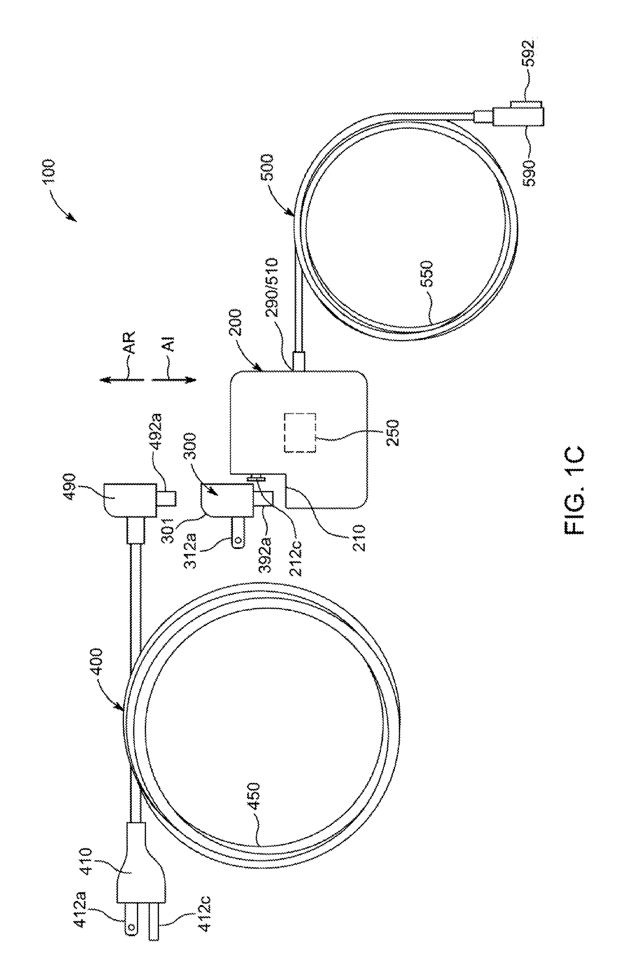
[0052]Power supply connector assemblies for power adapter systems and methods for making the same may be provided to reduce the risk of user exposure to live electrical contacts of the power supply connector assemblies during break events between portions of the power supply connector assemblies. A power adapter system may include a power adapter assembly for adapting and providing particular power to a user electronic device, and two or more interchangeable power supply connector assemblies for electrically coupling the power adapter assembly to an electric power supply. Due to the fact that an electrical connection between the power adapter assembly and an interchangeable power supply connector assembly of such a power adapter system may not be fixed but instead may be routinely terminated, one or more undesirable break events between portions of the system may be possible during use of the system. An outer housing of the power supply connector assembly may include a unibody five-...


PUM


Abstract

Power supply connector assemblies and methods for making the same are provided. An outer housing of the power supply connector assembly may include a unibody five-sided box-like structure and a set of power supply connector contacts may extend out therefrom for coupling to an electric power supply, while other portions of the set of power supply connector contacts may be electrically coupled to portions of a set of power adapter connector contacts within the outer housing. A protection body (e.g., a plastic insulation structure) may be positioned inside the outer housing for preventing user exposure to one or more live contacts of the power supply connector contacts when a portion of the outer housing is damaged or removed during a system break event.

Description

CROSS-REFERENCE TO RELATED APPLICATION(S)[0001]This application claims the benefit of prior filed U.S. Provisional Patent Application No. 62 / 611,192, filed Dec. 28, 2017, which is hereby incorporated by reference herein in its entirety.TECHNICAL FIELD[0002]This disclosure relates to power supply connector assemblies and, more particularly, to power supply connector assemblies with protected contacts.BACKGROUND OF THE DISCLOSURE[0003]Conventional power supply connector assemblies used for electrically coupling power adapter assemblies to electric power supplies are often susceptible to break events that expose live electrical contacts. Accordingly, alternative power supply connector assemblies are needed.SUMMARY OF THE DISCLOSURE[0004]Power supply connector assemblies and methods for making the same are provided.[0005]For example, in some embodiments, an assembly may be provided for being electrically coupled to a power supply contact of a power supply and to a power adapter contact ...

Claims


Application Information

Patent Timeline
Patent Type & Authority Applications(United States)
IPC IPC(8): H01R31/06H01R13/508H01R13/631H01R13/42
CPCH01R31/06H01R13/508H01R13/631H01R13/42H01R13/44H01R13/504H01R35/04H01R2103/00
Inventor YUAN, PAUL Z.KIM, MIN CHULLIU, XUAN
Owner APPLE INC
Why Eureka
Try Eureka