Method and device in wireless transmission

a wireless transmission and wireless technology, applied in the field of mobile communications, can solve problems such as problems such as reliability of wireless transmission, and achieve the effects of reducing the delay of retransmission, ensuring the quality of retransmission, and keeping the robustness of downlink transmission all the tim

Active Publication Date: 2019-07-04
SHANGHAI LANGBO COMM TECH CO LTD
View PDF0 Cites 4 Cited by
  • Summary
  • Abstract
  • Description
  • Claims
  • Application Information

AI Technical Summary

Benefits of technology

[0165]Compared with conventional schemes, the present disclosure has the following benefits.
[0166]The base station can select the transmission mode of downlink data flexibly according to the acquired CSI of a downlink channel targeting the served UE, thereby keeping the robustness of the downlink transmission all the time.
[0167]When the downlink channel CSI acquired previously fails due to some reasons (for example, movement of UE, etc.) and the UE cannot receive downlink data correctly, the base station can change to the beam sweeping scheme in time to transmit the retransmission data of the UE, thereby guaranteeing the quality of retransmission and reducing the delay of retransmission.

Problems solved by technology

Before the both sides of communication acquire partial channel information of each other, or in the case that the partial channel information acquired previously has failed, reliable wireless transmission becomes a problem.

Method used


Image

  • Method and device in wireless transmission
  • Method and device in wireless transmission
  • Method and device in wireless transmission

Examples


embodiment 1

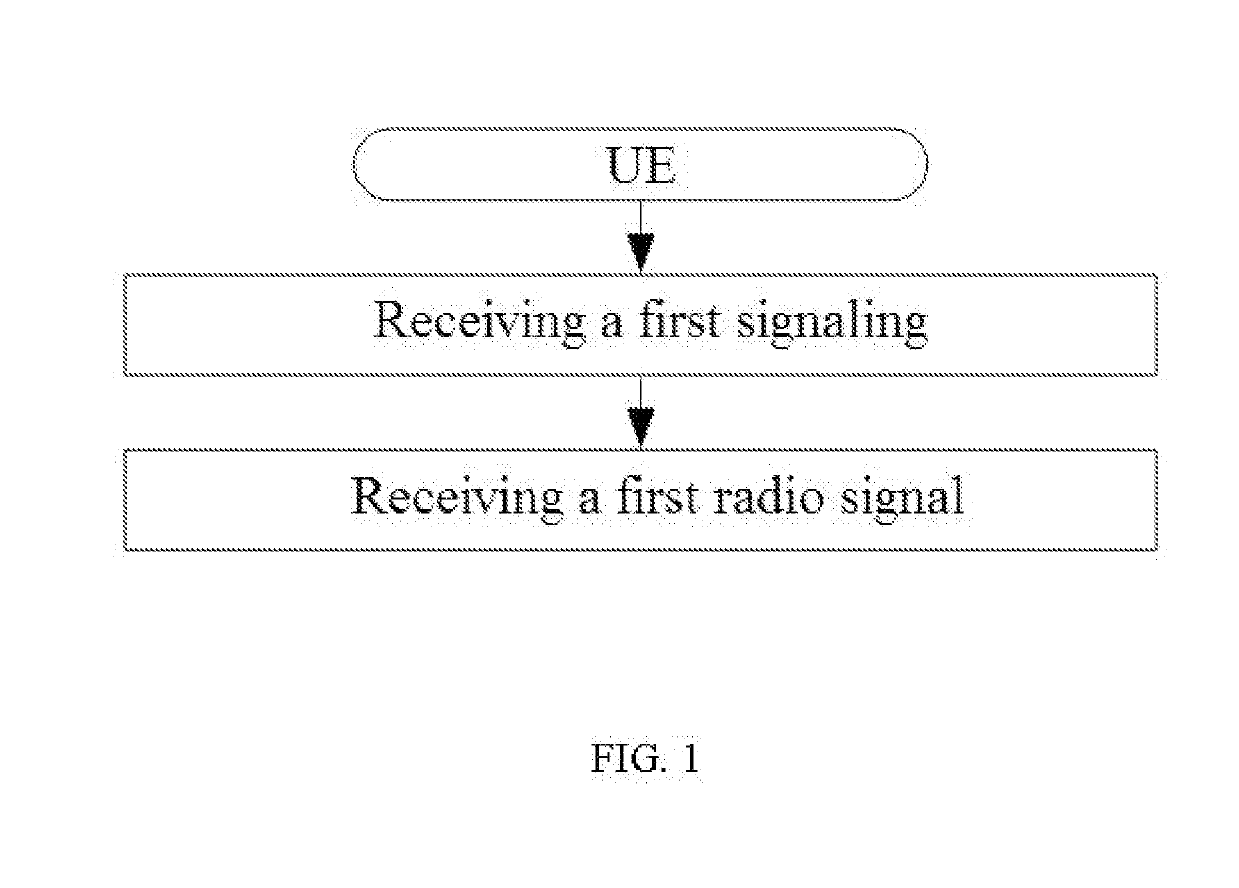
[0179]Embodiment 1 illustrates an example of a flowchart of a first signaling and a first radio signal, as shown in FIG. 1.

[0180]In Embodiment 1, the UE in the present disclosure receives a first signaling, and receives a first radio signal, the first radio signal carrying a first bit block. Herein, the first signaling is a physical layer signaling, the first signaling is used for determining a transmission format corresponding to the first radio signal, and the first bit block includes a positive integer number of bits; the transmission format corresponding to the first radio signal is one transmission format in a first format set, and the first format set includes a first transmission format and a second transmission format; a radio signal corresponding to the first transmission format includes P radio sub-signal(s), each of the P radio sub-signal(s) carries the first bit block, each of the P radio sub-signal(s) is transmitted by a same antenna port group, and the P is a positive ...

embodiment 2

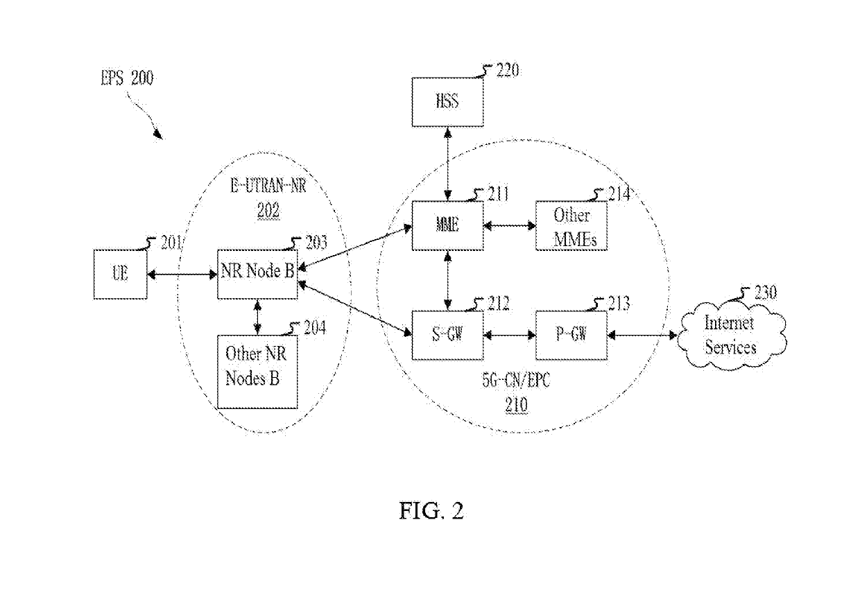
[0212]Embodiment 2 illustrates an example of a diagram of a network architecture, as shown in FIG. 2.

[0213]FIG. 2 illustrates a network architecture 200 of Long-Term Evolution (LTE), Long-Term Evolution Advanced (LTE-A) and future 50 systems. The LTE, LTE-A and 50 system network architecture 200 may be called an Evolved Packet System (EPS) 200. The EPS 200 may include one or more UEs 201, an Evolved UMTS Terrestrial Radio Access Network-New Radio (E-UTRAN-NR) 202, a 5G-Core Network / Evolved Packet Core (5G-CN / EPC) 210, a Home Subscriber Server (HSS) 220 and an Internet Service 230. Herein, the UMTS represents Universal Mobile Telecommunication System. The EPS may be interconnected with other access networks. For simple description, the entities / interfaces are not shown. As shown in FIG. 2, the EPS provides packet switching services. Those skilled in the art are easy to understand that various concepts presented throughout the present disclosure can be extended to networks providing c...

embodiment 3

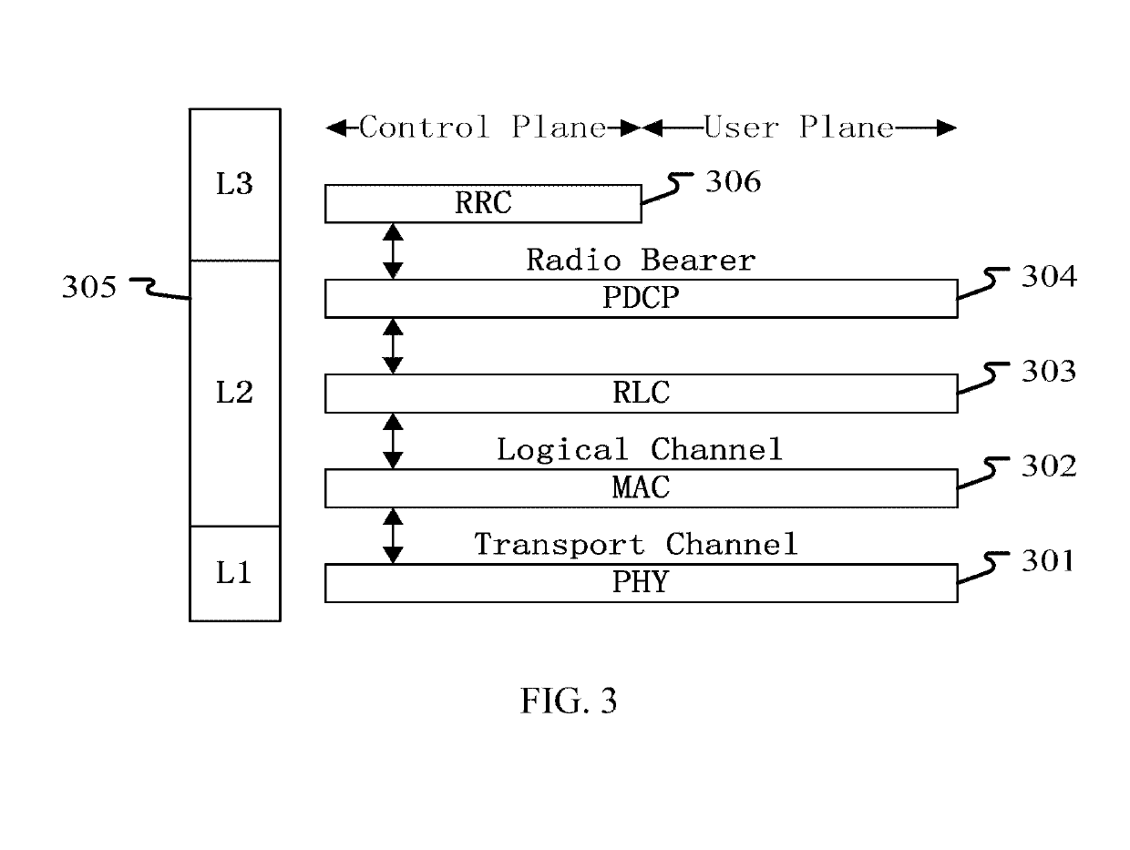
[0218]Embodiment 3 illustrates an example of a diagram of an embodiment of a radio protocol architecture of a user plane and a control plane, as shown in FIG. 3.

[0219]FIG. 3 is a diagram illustrating an embodiment of a radio protocol architecture of a user plane and a control plane. In FIG. 3, the radio protocol architecture of a UE and a gNB is represented by three layers, which are layer 1, layer 2 and layer 3 respectively. The layer 1 (L1) 301 is the lowest layer and performs signal processing functions of each PHY layer. The layer 1 is called PHY 301 in this paper. The layer 2 (L2) 305 is above the PHY 301, and is in charge of the link between the UE and the gNB via the PHY 301. In the user plane, the L2 305 includes a Medium Access Control (MAC) sublayer 302, a Radio Link Control (RLC) sublayer 303, and a Packet Data Convergence Protocol (PDCP) sublayer 304. All the three sublayers terminate at the gNB of the network side. Although not described in FIG. 3, the UE may include se...


PUM


Abstract

The present disclosure provides a method and a device in wireless transmission. A User Equipment (UE) first receives a first signaling, and then receives a first radio signal, the first radio signal carrying a first bit block. The first signaling is used for determining a transmission format corresponding to the first radio signal. The transmission format corresponding to the first radio signal is one transmission format in a first format set, and the first format set comprises a first transmission format and a second transmission format. A radio signal corresponding to the first transmission format includes P radio sub-signal(s), each one of the P radio sub-signal(s) carries the first bit block, and the P radio sub-signal(s) is(are) transmitted by a same antenna port group.

Description

CROSS REFERENCE TO RELATED APPLICATION[0001]This application is a continuation-in-part of International Application No. PCT / CN2017 / 092479, filed Jul. 11, 2017, claiming the priority benefit of Chinese Patent Application Serial Number 201610590751.2, filed on Jul. 25, 2016, the full disclosure of which is incorporated herein by reference.BACKGROUNDTechnical Field[0002]The present disclosure relates to methods and devices for multi-antenna transmission in the technical field of mobile communications, and in particular to a wireless communication scheme in scenarios that a base station side is deployed with a large number of antennas.Related Art[0003]Massive Multi-Input Multi-Output (MIMO) becomes one research hotspot of next-generation mobile communications. In the massive MIMO, multiple antennas experience beamforming to form a relatively narrow beam which points to a particular direction to improve the quality of communication. Generally, the beam formed by multiple antennas through...

Claims


Application Information

Patent Timeline
Patent Type & Authority Applications(United States)
IPC IPC(8): H04W72/08H04B7/0404H04B7/0417H04J3/16H04B7/06H04L5/00
CPCH04W72/085H04B7/0404H04B7/0417H04J3/1694H04B7/0626H04L5/0053H04B7/0617H04L1/0693H04B7/0689H04L5/0057H04L5/0023H04W72/542
Inventor ZHANG, XIAOBO
Owner SHANGHAI LANGBO COMM TECH CO LTD
Why Eureka
Try Eureka