Flight vehicle with drone and lift-producing protrusion

a drone and protruding technology, applied in hybrid airships, collapsible antennas, instruments, etc., can solve the problem of limited dwell of drones alon

Active Publication Date: 2019-07-11
RAYTHEON CO
View PDF0 Cites 6 Cited by
  • Summary
  • Abstract
  • Description
  • Claims
  • Application Information

AI Technical Summary

Benefits of technology

[0004]A flight vehicle includes a pair of protrusions, one of which provides buoyant lift.

Problems solved by technology

Drones alone provide limited dwell, especially after climbing to altitude and position.

Method used


Image

  • Flight vehicle with drone and lift-producing protrusion
  • Flight vehicle with drone and lift-producing protrusion
  • Flight vehicle with drone and lift-producing protrusion

Examples


Embodiment Construction

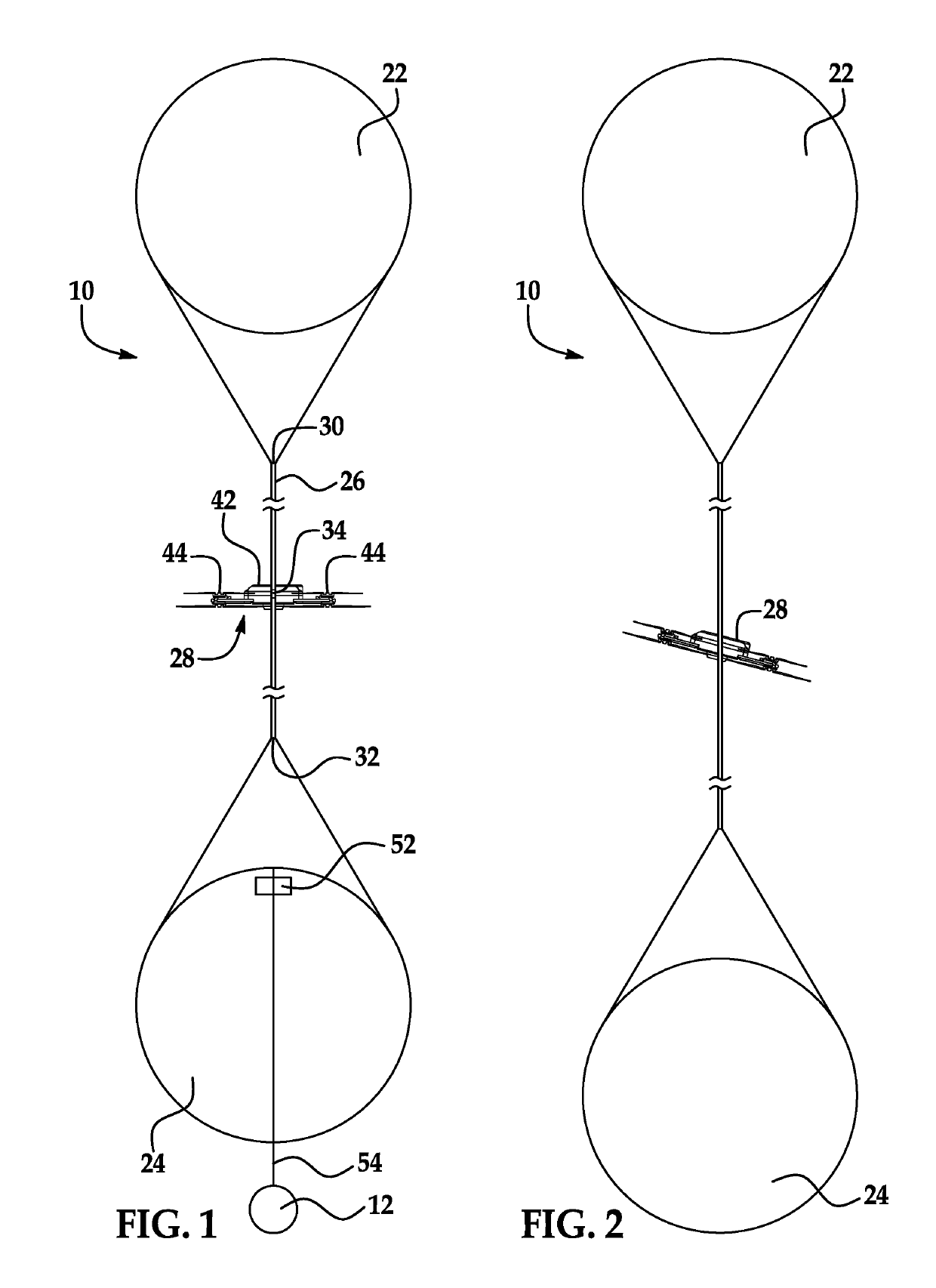
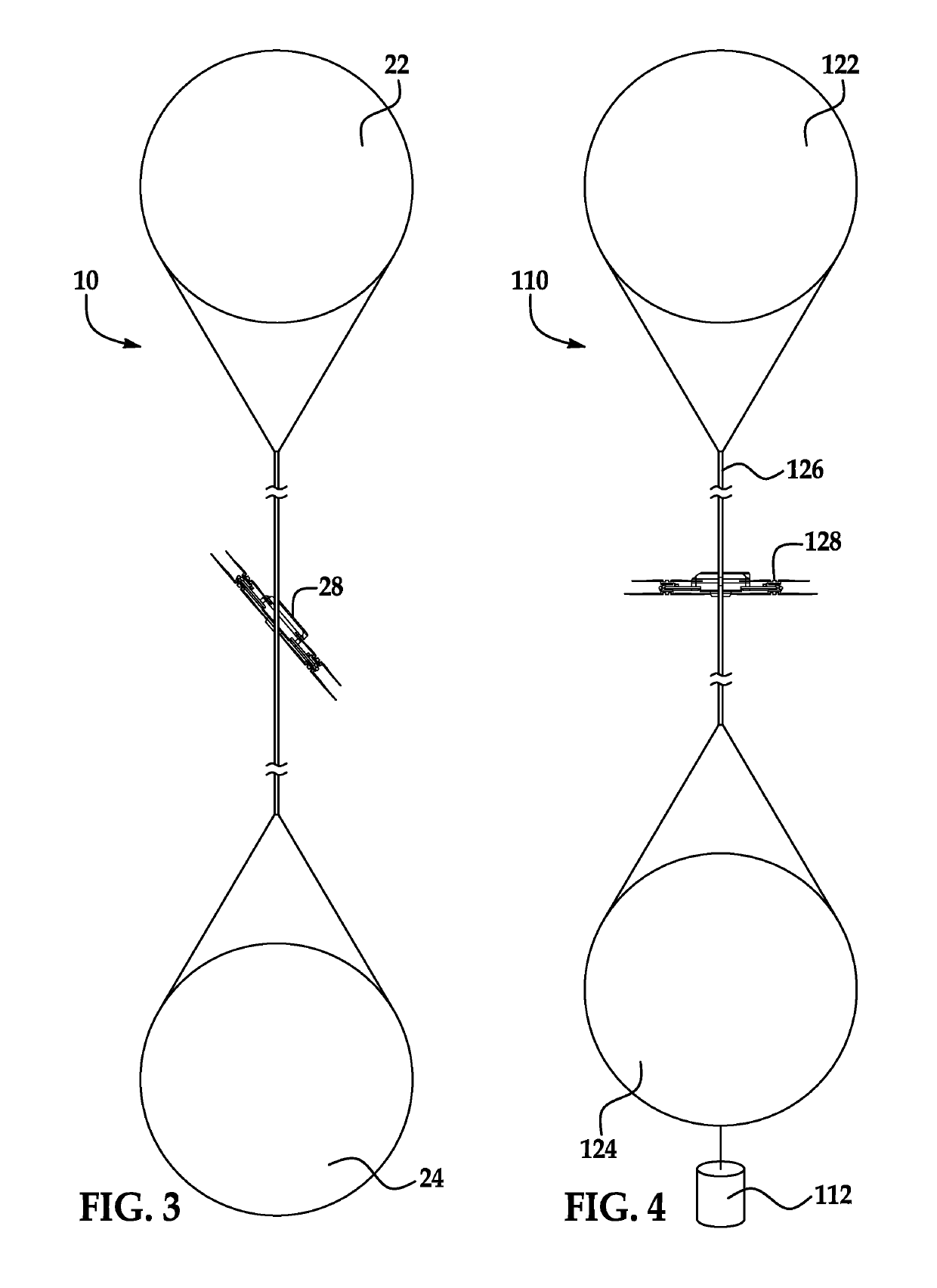
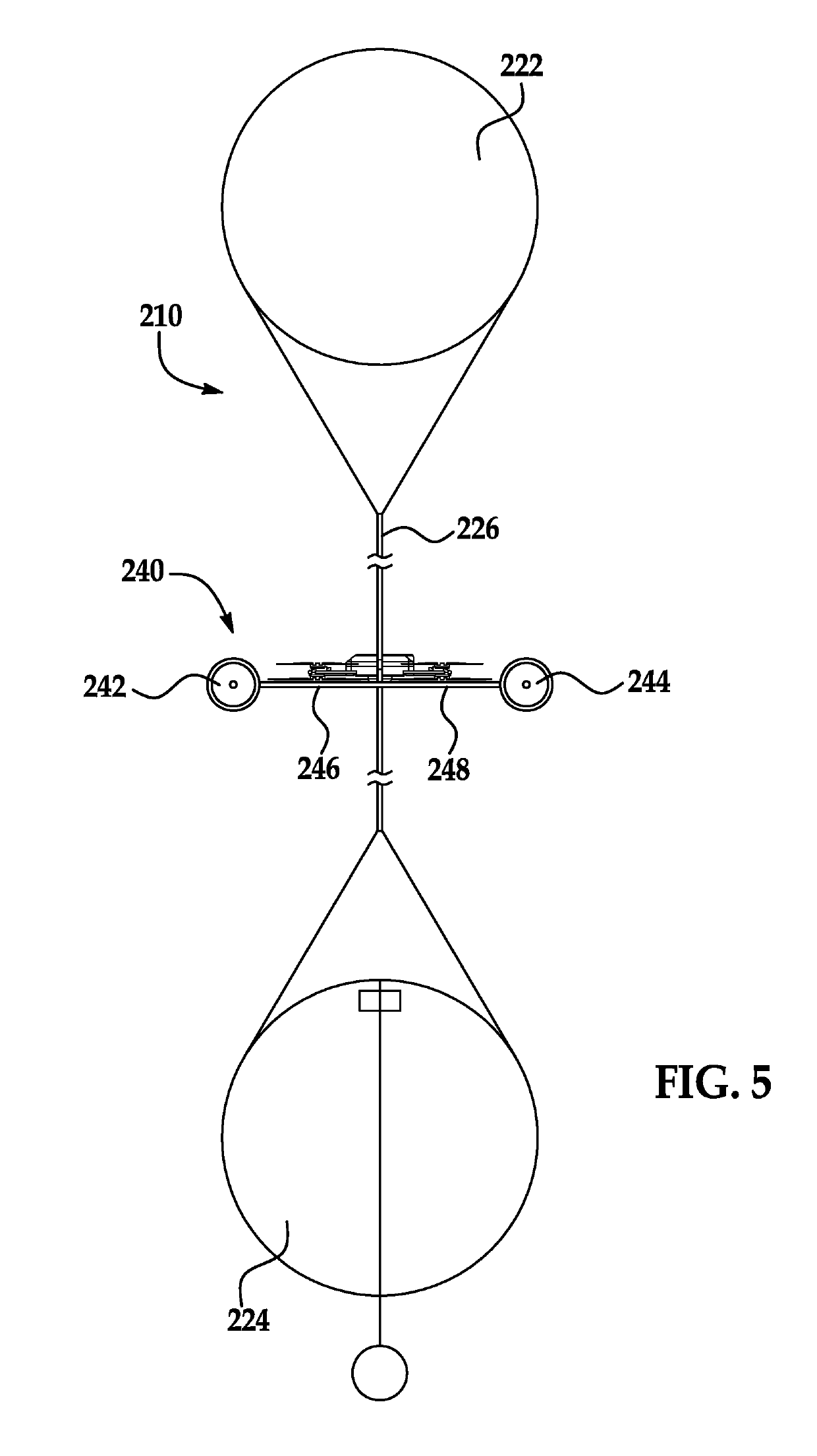
[0038]A flight vehicle includes a drone with a pair of shaped protrusions mechanically coupled to the drone. One of the shapes is a hollow lift-producing shape, such as being a balloon filed with a lighter-than-air gas, and the other of the shapes is below the drone. The shape below the drone may be a hollow shape that does not produce lift, for example being a balloon filled with air. The shapes may be similar in size and shape, so as to provide similar drag characteristics. The shapes may be opposite ends of a support, such as a stick, rod, or other (relatively) slender structure. The vehicle includes a payload, such as radar calibration equipment or an antenna. The drone may be used to counteract wind forces on the flight vehicle, and / or to otherwise position the flight vehicle. The lift-producing hollow shape and the drone may be used in combination in positioning the flight vehicle. The drone may be coupled to a central section of the support, with the drone able to tilt relati...


PUM


Abstract

A flight vehicle includes a drone with a pair of shaped protrusions mechanically coupled to the drone. One of the shapes is a hollow lift-producing shape, such as being a balloon filed with a lighter-than-air gas, and the other of the shapes is below the drone. The shape below the drone may be a hollow shape that does not produce lift, for example being a balloon filled with air. The shapes may be similar in size and shape, so as to provide similar drag characteristics. The shapes may be opposite ends of a support, such as a stick, rod, or other (relatively) slender structure. The vehicle includes a payload, such as radar calibration equipment or an antenna. The drone may be used to counteract wind forces on the flight vehicle, and/or to otherwise position the flight vehicle.

Description

FIELD OF THE INVENTION[0001]The invention is in the field of flight vehicles, in particular for flight vehicle that are able to maintain flight in one place for long periods of time.DESCRIPTION OF THE RELATED ART[0002]Radars require periodic calibration for system changes such as transmit and receive exciter outages or other changes to arrays and radar systems. A convenient calibration sphere can be balloon lofted but is often at the whims of weather, and launch intercept probability based on beam pointing restrictions and limited dwell. It is far better to have a maneuverable radar calibration sphere, and one that can be deployed to desired altitudes and locations. It is also desirable to lower the sphere to desired separation from a drone. Drones alone provide limited dwell, especially after climbing to altitude and position. The lowering of the sphere and recovery also reduce the dwell.[0003]Other situations call for payloads / equipment to be kept aloft for an extended period of t...

Claims


Application Information

Patent Timeline
Patent Type & Authority Applications(United States)
IPC IPC(8): B64C39/02
CPCB64C39/024B64C2201/027B64C2201/108B64C2201/101B64C2201/12G01S7/4004B64B1/34B64B1/44B64B1/54B64B1/70G01S7/4052H01Q1/082H01Q1/2291H01Q1/28H01Q1/34B64B2201/00G01S7/4082B64U10/30B64U10/13B64U30/20B64U2101/00
Inventor HEINEN, GREGORY W.
Owner RAYTHEON CO
Why Eureka
Try Eureka