Unlock instant, AI-driven research and patent intelligence for your innovation.

Imaging apparatus, imaging control method, and storage medium

Inactive Publication Date: 2019-07-11
CANON KK
View PDF0 Cites 1 Cited by
  • Summary
  • Abstract
  • Description
  • Claims
  • Application Information

AI Technical Summary

Benefits of technology

The patent is about an imaging device that can increase the frame rate while reducing the distortion caused by the rolling shutter. It uses a mechanical shutter to improve the quality of the image.

Problems solved by technology

However, the shutter disclosed in JP 2-134625 used for the imaging apparatus having the image sensor causes the following problem.
In general, in the slit exposure that moves the two mechanical curtains, an object moving in a direction orthogonal to the traveling directions of the mechanical curtains causes a rolling shutter distortion that distorts an image due to the charge accumulation timing shifts in the image sensor from the exposure start to the exposure end.
In other words, the different rolling shutter distortions alternate between the odd-numbered images acquired by the forward travel exposure and the even-numbered images acquired by the backward travel exposure, and impairs the image continuity.
As a result, the user who is accustomed to the conventional rolling shutter distortion gets confused.

Method used


Image

  • Imaging apparatus, imaging control method, and storage medium
  • Imaging apparatus, imaging control method, and storage medium
  • Imaging apparatus, imaging control method, and storage medium

Examples


first embodiment

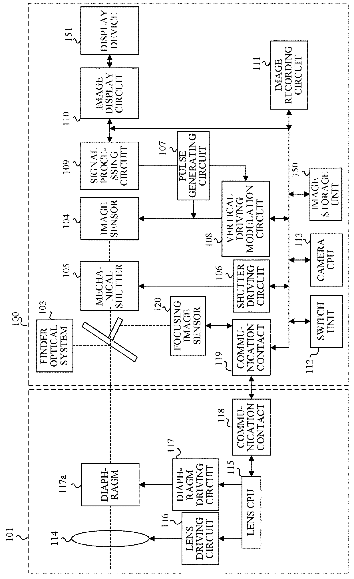
[0027]FIG. 1 illustrates an imaging apparatus (referred to as a camera body hereinafter) 100 according to a first embodiment of the present invention and an interchangeable lens unit (simply referred to as a lens unit hereinafter) 101 detachably mounted on the camera body 100. The configuration of the lens unit 101 will now be described.

[0028]An imaging lens 114 as an imaging optical system forms an object image by forming light from an object. In the drawing, the imaging lens 114 is expressed by a single lens, but actually includes a plurality of lenses such as a focus lens and a magnification-varying lens.

[0029]A lens CPU 115 controls focus driving and zoom driving of the imaging lens 114 via a lens driving circuit 116, and controls driving of a diaphragm (aperture stop) 117a via a diaphragm driving circuit 117. The lens CPU 115 communicates with the camera CPU 113 in the camera body 100 to be described later via a communication contact 118 in the lens unit 101 and a communication...

second embodiment

[0082]Next follows a description of a second embodiment according to the present invention. The camera body 100 according to this embodiment has the same configuration as that of the first embodiment, but the shutter blade A serves as the rear curtain in the forward travel imaging and the shutter blade B serves as the rear curtain in the backward travel imaging. This embodiment operates or moves the front curtain by the electronic shutter (referred to as an electronic front curtain hereinafter) prior to moving the rear curtain in each of the forward travel imaging and the backward travel imaging.

[0083]Referring now to FIGS. 9A and 9B, a description will be given of the forward travel exposure and the backward travel exposure according to this embodiment. FIGS. 9A and 9B illustrate the shutter blade A (200a), the shutter blade B (200b), and the image sensor 104 (the charge accumulation area 6) viewed from the lens unit 101 side. In this embodiment, the imaging plane 14 on the image s...


PUM


Abstract

An imaging apparatus includes an image sensor, a mechanical shutter configured to travel in a first direction and a second direction different from the first direction relative to an imaging plane of the image sensor, and a control unit configured to control imaging about an operation of the mechanical shutter. The control unit provides first imaging that causes the mechanical shutter to travel in the first direction in synchronization with an exposure of the image sensor and second imaging that causes the mechanical shutter to travel in the second direction in synchronization with the exposure of the image sensor. The control unit determines whether to perform one of the first imaging and the second imaging or to perform both the first imaging and the second imaging continuously based on an imaging mode and predetermined information on an imaging scene.

Description

CROSS-REFERENCE TO RELATED APPLICATIONS[0001]This application is a Continuation of International Patent Application No. PCT / JP2017 / 033744, filed on Sep. 19, 2017, which claims the benefit of Japanese Patent Application No. 2016-188090, filed on Sep. 27, 2016, both of which are hereby incorporated by reference herein in their entirety.BACKGROUND OF THE INVENTIONField of the Invention[0002]The present invention relates to an imaging apparatus having a plurality of mechanical shutters with different traveling (moving) directions in exposing an image sensor.Description of the Related Art[0003]Some imaging apparatuses include a shutter with a mechanical front curtain configured to control an exposure start and a mechanical rear curtain configured to control an exposure end. Other imaging apparatuses have an electronic front curtain configured to electronically realize a function similar to that of the mechanical front curtain by rest scanning that resets electric charges in an image sens...

Claims


Application Information

Patent Timeline
IPC IPC(8): G03B9/14G03B7/093G03B9/18
CPCG03B9/14G03B7/093G03B9/18G03B9/36G03B9/42H04N23/81H04N23/689H04N23/73H04N23/60
Inventor HONDA, HIROYA
Owner CANON KK