Diagnostic drainage catheter assembly & methods

a technology of diagnostic drainage catheter and catheter assembly, which is applied in the field of diagnostic drainage catheter assembly & methods, can solve the problems of long deployment, pain, bladder injury and/or urine reflux through the ureters into the kidneys, and inability to adequately empty the bladder

Active Publication Date: 2019-07-18
SRS MEDICAL SYST INC
View PDF0 Cites 5 Cited by
  • Summary
  • Abstract
  • Description
  • Claims
  • Application Information

AI Technical Summary

Benefits of technology

[0030]A diagnostic drainage catheter assembly is further contemplated. The assembly is generally characterized by an indwelling urinary catheter, an apparatus for sensing, measuring, or monitoring select patient urodynamic parameters, and an assembly for operably uniting the apparatus with a bladder anchoring balloon of the indwelling urinary catheter. The indwelling urinary catheter is characterized by a urine drainage lumen, a bladder anchoring balloon, a balloon inflation valve, and a balloon filling lumen operably linking the balloon inflation valve wit

Problems solved by technology

Excessive urine accumulation in the bladder may cause pain, bladder injury and/or reflux of urine through the ureters into the kidneys.
Most catheters are a short term fix (i.e., temporary), necessary only until the ability to self-void can be reliably and safely demonstrated, however, circumstances abound which warrant a lengthy deployment (i.e., chronic).
Urinary retention often occurs when the bladder vesical pressure does not adequately overcome the bladder outlet resistance, resulting in an inability to adequately empty the bladder.
Hospitals and urology practices have difficultly predicting when an individual no longer needs a urinary catheter to empty his or her bladder.
The use of urinary catheters comes with a high incidence of medical complications, including urinary tract infections, known as catheter associated urinary tract infections (CAUTIs), the most common type of healthcare associated infectio

Method used


Image

  • Diagnostic drainage catheter assembly & methods
  • Diagnostic drainage catheter assembly & methods
  • Diagnostic drainage catheter assembly & methods

Examples


Embodiment Construction

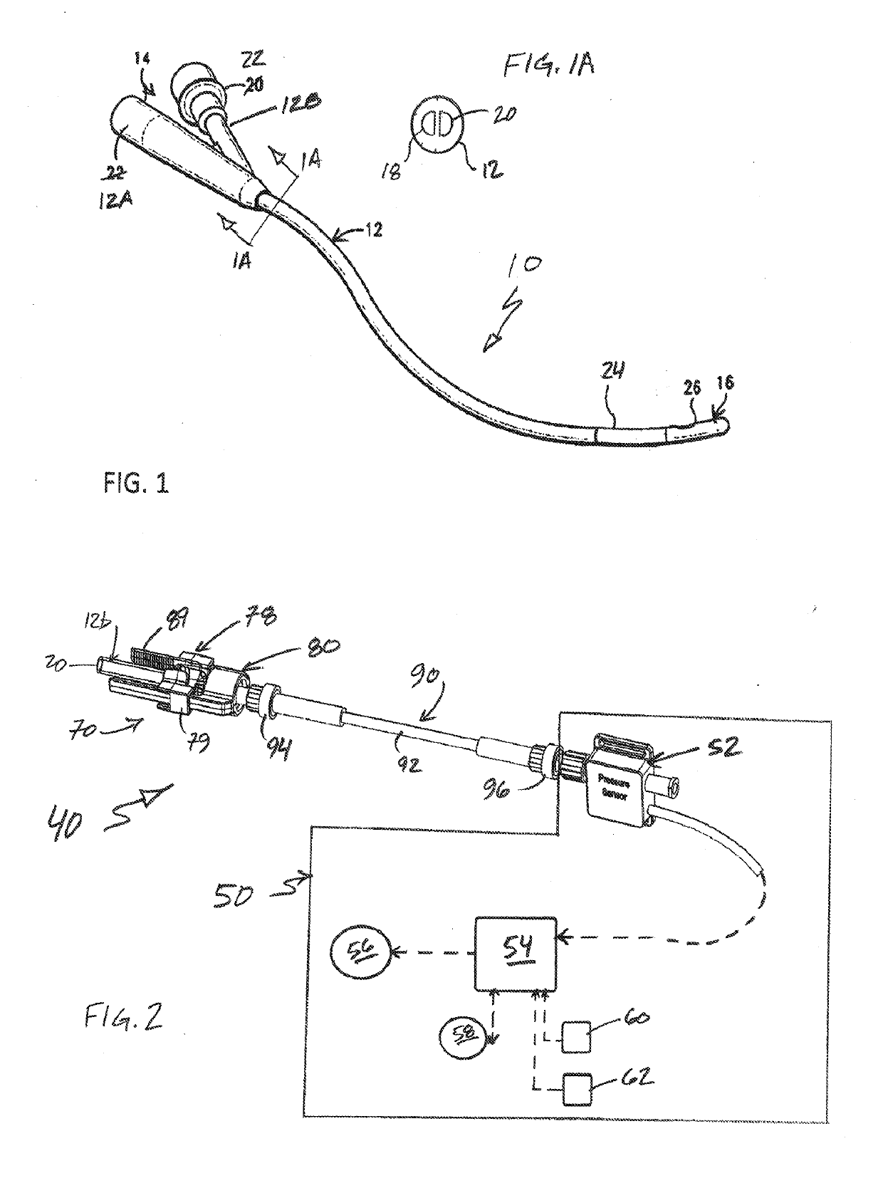
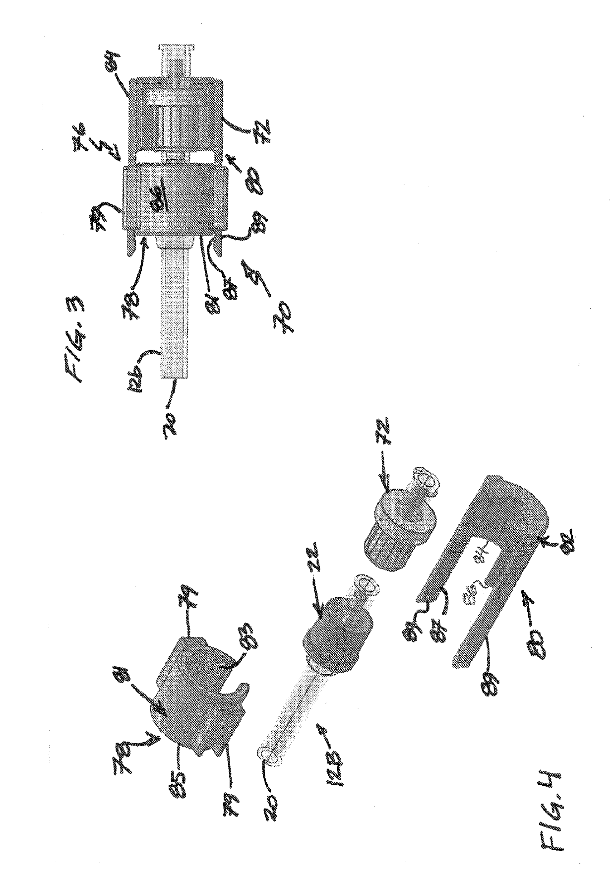
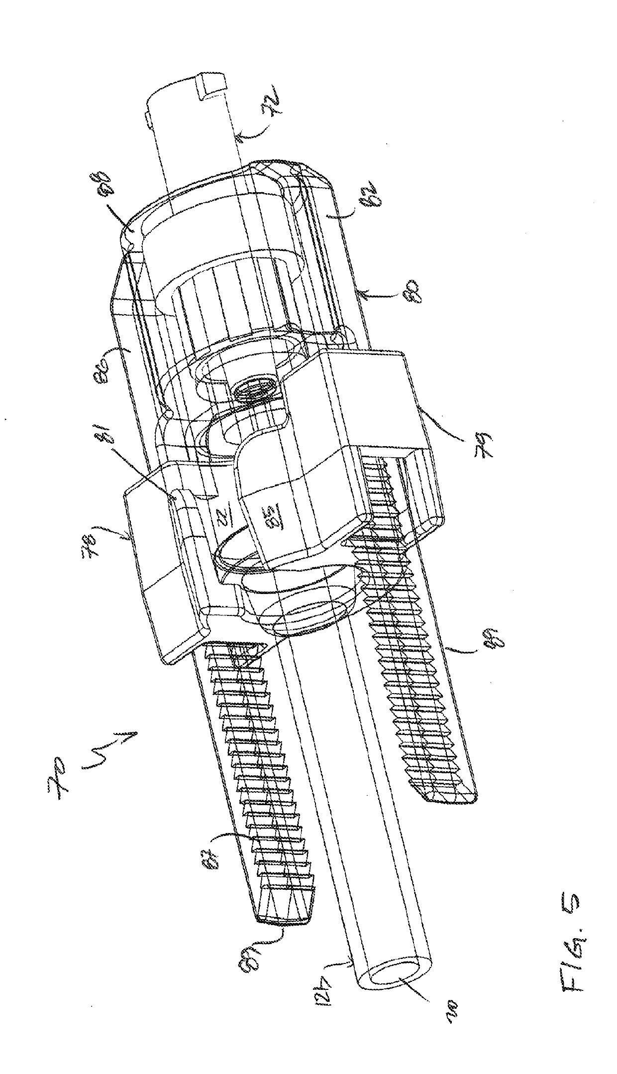
[0045]Preferred, non-limiting systems, kits, assemblies, structures and / or mechanisms relating to and enabling assessment of patient urodynamics are generally disclosed, presented and / or represented throughout the figures of the subject disclosure. An advantageous, non-limiting system is generally depicted in FIG. 2 for operative combination with the indwelling urinary catheter of FIG. 1. Several advantageous, non-limiting adaptor assemblies of the contemplated system are generally depicted in each of FIGS. 3, 5 & 6, the remaining figures directed to particulars for / of select depicted assemblies. In advance of particulars for or with regard to the instant diagnostic drainage catheter system, in all contemplated and / or disclosed forms, some preliminary observations and / or comments as to Applicant's diagnostic approach are set forth.

[0046]Advantageously, Applicant's diagnostic approach is directed to individuals (i.e., patients) that have been catheterized and are, at the time of asse...


PUM


Abstract

A vesical pressure measurement system is provided. One or more elements of the system are operably combinable with a previously deployed urinary drainage catheter. The system includes a urodynamic data system and a urinary drainage catheter balloon adaptor. The data system is characterized by a pressure sensor for vesical pressure measurement, and a processor/controller for receiving, processing and/or displaying select urodynamic patient parameters comprising sensed/monitored pressure data. The adaptor operably unites the pressure sensor of the data system to a balloon inflation valve of the catheter. The adaptor includes an adaptor valve for connection to the balloon inflation valve, and a housing, the housing including a balloon inflation valve portion and an adaptor valve portion, the portions urgingly uniteable in furtherance of establishing and maintaining a secure interface between the balloon inflation valve and the adaptor valve.

Description

[0001]This is an international patent application filed under 35 USC § 363 claiming priority under 35 U.S.C. § 119(e) to the U.S. patent application Ser. No. 15 / 695,249 filed Sep. 5, 2017 pursuant to 35 USC § 111(a) claiming priority under 35 USC § 120 of / to U.S. Pat. Appl. Ser. No. 62 / 510,795 filed May 25, 2017, U.S. Pat. Appl. Ser. No. 62 / 467,520 filed Mar. 6, 2017, and U.S. Pat. Appl. Ser. No. 62 / 408,908 filed Oct. 17, 2016, each entitled DIAGNOSTIC DRAINAGE CATHETER ASSEMBLY, the disclosures of which are hereby incorporated by reference in their entireties.TECHNICAL FIELD[0002]The present invention is generally directed to one or more of kits, systems, assemblies, subassemblies, apparatuses, devices, and / or methods for / of measuring / obtaining bladder vesical pressure using a urinary drainage catheter, more particularly still, to any of such items and / or methods characterized by use of a balloon fluid fill port of a urinary drainage catheter to ascertain vesical pressure and the l...

Claims


Application Information

Patent Timeline
IPC IPC(8): A61B5/00A61M25/10A61B5/04A61B5/03A61M25/00A61B5/0488
CPCA61B5/6853A61M25/10185A61B5/04012A61B5/036A61M25/0017A61B5/0488A61B5/205A61B5/208A61M39/22A61B5/316A61B5/389
Inventor BRODY, LEE
Owner SRS MEDICAL SYST INC
Why Eureka
Try Eureka