Folding knife configured for safe and rapid disassembly and reassembly

Active Publication Date: 2019-07-18
LO YEN FEN
View PDF29 Cites 6 Cited by
  • Summary
  • Abstract
  • Description
  • Claims
  • Application Information

AI Technical Summary

Benefits of technology

The present invention is a folding knife that can be safely and rapidly disassembled and reassembled. The inventor incorporated practical experience and knowledge of knife design and manufacture, and researched and experimented to overcome the problems and drawbacks of conventional folding knives that users have to disassemble and reassemble. The technical effect of the invention is greater convenience and safety of use than conventionally achievable.

Problems solved by technology

However, a conventional folding knife that has been used for a long time tends to have a buildup of grime in the handle, in addition to a worn, and hence blunt, blade.
While this conventional manufacturing method can keep the handle and the blade of a conventional folding knife from separating from each other due to the improper intervention of an external force during use, the securely fastened handle structure adds to the difficulty of disassembly of the conventional folding knife; in other words, the conventional folding knife cannot be easily, safely, or rapidly taken apart for cleaning or maintenance.
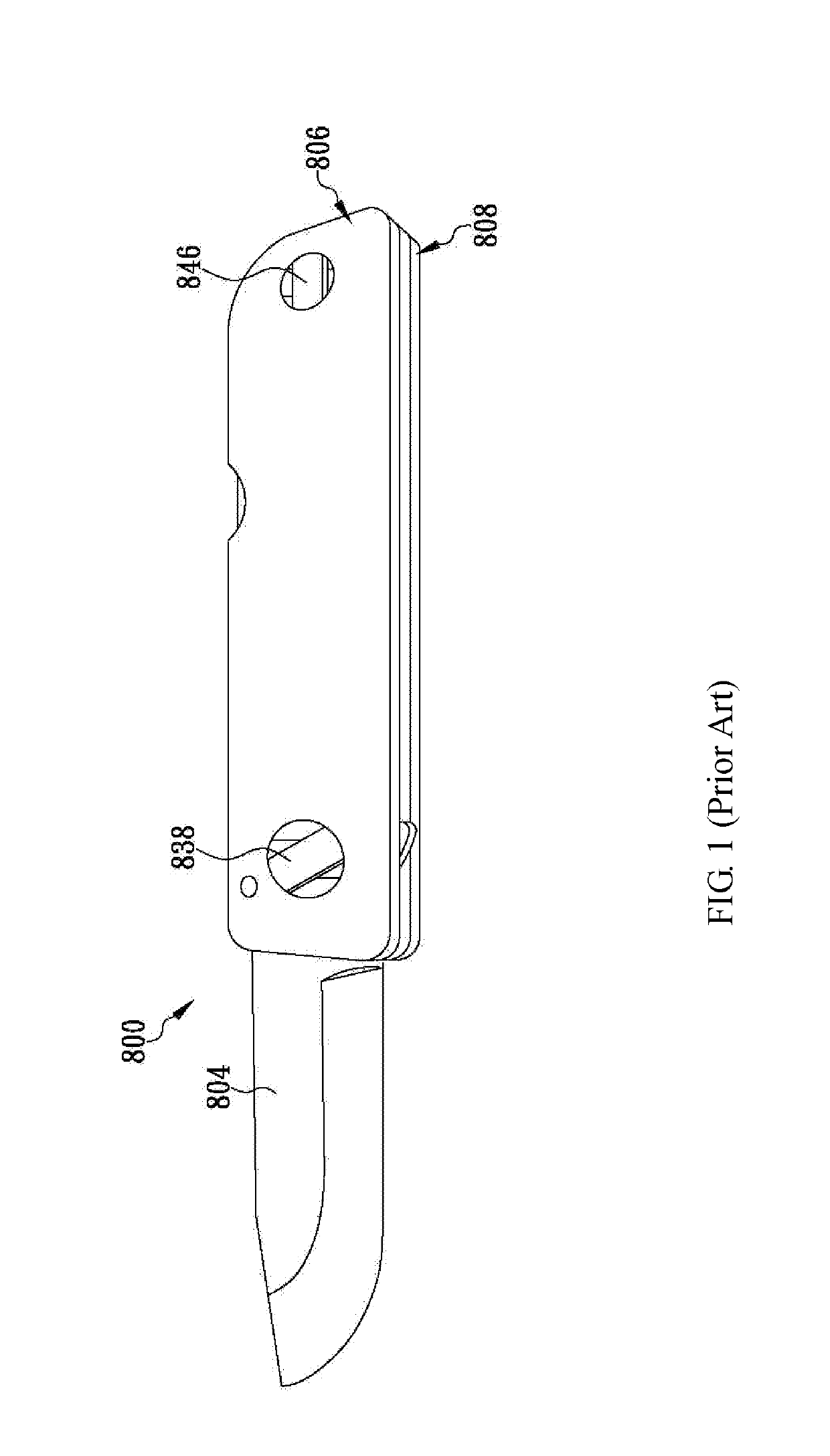
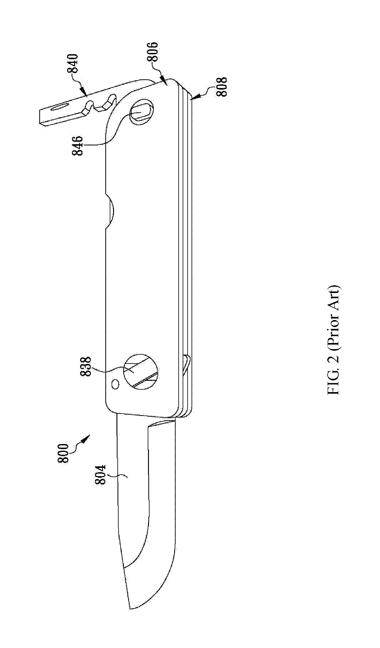
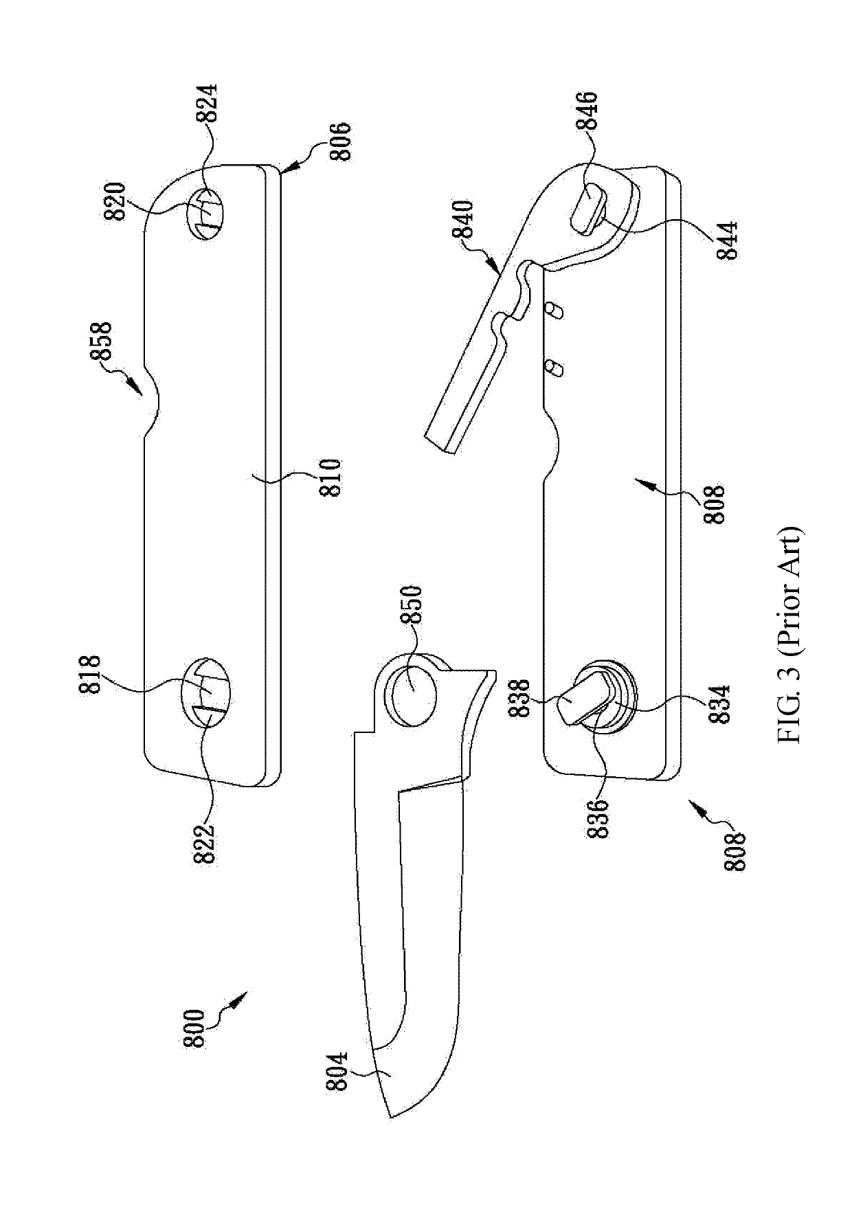
(1) While disassembling or reassembling the folding knife 800, a user must sequentially and repeatedly adjust the upper handle portion 806, the lower handle portion 808, and the locking portion 840 to their respective required positions with precision while gripping each of the aforesaid components with one or the other hand. Not only does the adjustment complicate the disassembly and reassembly of the folding knife 800 and therefore cause trouble to the user, but also the user's fingers or palms may be cut during the disassembly or reassembly process if the blade 804 is not gripped at an appropriate angle or by an appropriate portion.
(2) The blocks 838, 846 and the openings 818, 820 are not circular but have specific polygonal shapes. These structural features require precision machining during manufacture and hence incur high machining costs. In addition, one who tries to disassemble or reassemble the folding knife 800 must adjust the positions of the blocks 838, 846 and of the corresponding openings 818, 820 very carefully because the blocks 838, 846 cannot be inserted through the openings 818, 820 respectively unless the former are aligned with the latter. Undoubtedly, the time-consuming and difficult aligning process makes it difficult to disassemble and reassemble the folding knife 800.
(3) The thicknesses of the engaging blocks 822, 824 must be equal to or slightly smaller than the depths of the engaging grooves 836, 844 respectively in order for the engaging blocks 822, 824 to engage respectively with the engaging grooves 836, 844 and thereby bring about a locked state after the upper handle portion 806, the lower handle portion 808, and the locking portion 840 are rotated. It is consequently required that the manufacturing tolerances of the related components of the folding knife 800 be controlled within a very small range; otherwise, either the folding knife 800 may have problem being assembled, or the components may get loose or make noise after the folding knife 800 is forced into the assembled state, resulting in a high fraction defective corrigible only through precision machining. Such machining, however, leads to high production cost and may thus hinder the popularization of the folding knife 800 and similar products that feature easy disassembly and reassembly.
(4) While the folding knife 800 is being disassembled or reassembled, friction and compression between the edges of the engaging blocks 822, 824 and the edges of the engaging grooves 836, 844 are inevitable. After long-term use, therefore, the edges of the engaging blocks 822, 824 or of the engaging grooves 836, 844 are bound to be damaged or deformed. Once the damage or deformation aggravates over time, engagement between the engaging blocks 822, 824 and the engaging grooves 836, 844 may become impossible, and in that case, the folding knife 800 can no longer be disassembled and reassembled as designed.
(5) The folding knife 800 is so configured that only after the blocks 838, 846 and the corresponding openings 818, 820 are adjusted precisely to the correct corresponding positions can the blocks 838, 846 be inserted with ease through the openings 818, 820 respectively. If the folding knife 800 is of a relatively small size, the blocks 838, 846 and the corresponding openings 818, 820 will be, too, making it more difficult to align the blocks 838, 846 with the openings 818, 820 respectively, and the difficulty of, and danger associated with, disassembling and reassembling the folding knife 800 will increase significantly as a result.
As stated above, the conventional folding knives do have a large number of problems and drawbacks to be overcome.

Method used


Image

  • Folding knife configured for safe and rapid disassembly and reassembly
  • Folding knife configured for safe and rapid disassembly and reassembly
  • Folding knife configured for safe and rapid disassembly and reassembly

Examples


Embodiment Construction

[0030]The present invention provides a folding knife configured for safe and rapid disassembly and reassembly. Referring to FIG. 6 for a preferred embodiment of the invention, the folding knife at least includes an upper handle portion 10, a lower handle portion 11, a spacer 12, an engaging and pivotally connecting shaft 30, an engaging and locking shaft 40, a blade 20, and a pushable locking member 50. The upper handle portion 10 is formed with a front engaging groove 101 adjacent to and extending toward the front end of the upper handle portion 10. The front engaging groove 101 has a flared section adjacent to and flaring toward the front end of the front engaging groove 101. The rear end of the front engaging groove 101 is curved (or semicircular). The upper handle portion 10 is further formed with a rear engaging groove 102 adjacent to the rear end of the upper handle portion 10. The rear engaging groove 102 also extends toward the front end of the upper handle portion 10 and ha...


PUM


Abstract

A folding knife configured for safe and rapid disassembly and reassembly includes an upper handle portion having two engaging grooves respectively adjacent to its two ends, and a lower handle portion having an engaging and pivotally connecting shaft and an engaging and locking shaft respectively adjacent to its two ends. The two shafts are engageable in the engaging grooves respectively. A blade is mounted around the engaging and pivotally connecting shaft and rotatable into and out of a space between the handle portions. A pushable locking member is rotatably connected to the engaging and locking shaft and can be pushed to allow or prevent disengagement between the engaging and locking shaft and the corresponding engaging groove. Thus, user only has to push the pushable locking member, the upper handle portion and the blade will be in a detachable from or securely connected to the lower handle portion as a whole.

Description

FIELD OF THE INVENTION[0001]The present invention relates to a folding knife. More particularly, the invention relates to a folding knife with an engaging and locking shaft on a lower handle portion, an engaging groove in an upper handle portion, and a pushable locking member for pushing the engaging and locking shaft into a locked mode, in which the engaging and locking shaft is kept from disengaging from the engaging groove and thereby ensures secure pivotal connection between the handle portions and the blade of the folding knife.BACKGROUND OF THE INVENTION[0002]Commercially available folding knives are typically composed of a handle and a blade, wherein the blade is pivotally connected to the handle in order to be rotated about the pivot joint and thereby moved out of or stored into the handle. Such a folding knife can be easily and safely carried around for use because it is compact in size and has the blade stored in the handle when folded. Compared with knives whose blade can...

Claims


Application Information

Patent Timeline
IPC IPC(8): B26B1/04B26B5/00B26B1/10
CPCB26B1/04B26B5/00B26B1/10B26B1/044
Inventor LO, YEN-FEN
Owner LO YEN FEN
Why Eureka
Try Eureka