Apparatus and method for placing and tensioning an aerial rope through a traveler of a power line

a technology of aerial rope and traveler, which is applied in the field of apparatus and a method of tensioning an aerial rope, can solve the problems of high cost of operator, local use permits, and high cost of helicopter equipment, so as to increase the braking force of the tensioning mechanism, the effect of quick connection and disconnecting

Active Publication Date: 2019-07-18
QUANTA ASSOC
View PDF0 Cites 14 Cited by
  • Summary
  • Abstract
  • Description
  • Claims
  • Application Information

AI Technical Summary

Benefits of technology

[0007]In another example, an apparatus for tensioning a rope that is attached to an airborne unmanned aerial device may utilize a pulling rope reel including a cylinder around which the rope is wound, a shaft that longitudinally passes through the cylinder, a disc brake rotor that is mounted to the shaft, a brake caliper that is mounted circumferentially about a periphery of the disc brake rotor, a brake lever that is movable to control movement of the brake caliper against the disc brake rotor, and a protruding hitch portion that inserts to a vehicle receiver hitch for quickly connecting and disconnecting the apparatus for tensioning a rope. The apparatus may further utilize a control cable having a control cable first end attached to the brake lever, and a control cable second end attached to the brake caliper, a frame, such that the protruding hitch portion protrudes from the frame, a pulling rope guide mounted to a frame and through which the rope is threaded, and a hinge that permits adjustment of the pulling rope guide support.
[0008]In another example, a method of flying a rope may include positioning a vehicle next to a series of power line structures or towers, fastening a rope tensioning mechanism to the vehicle, pulling a rope from the rope tensioning mechanism, connecting the rope to an unmanned aerial device, releasing a brake of the unmanned aerial device, flying the unmanned aerial device away from the vehicle, unwinding the rope from a cylinder of the tensioning mechanism, and increasing braking force of the tensioning mechanism thereby increasing tension in the rope as the unmanned aerial device flies away from the vehicle. The method may further include disconnecting the rope from the unmanned aerial device, decreasing braking force of the tensioning mechanism, and rewinding the rope around a cylinder of the tensioning mechanism. Fastening a rope tensioning mechanism to the vehicle may further include inserting an insertion bar of the tensioning mechanism, or a frame of the tensioning mechanism, into a trailer hitch on the vehicle. Rewinding the rope around a cylinder of the tensioning mechanism may be accomplished using a hand crank, an electric drill, or an electric motor with a sufficient torque rating attached or mated to a shaft of the cylinder. Increasing braking force of the tensioning mechanism and decreasing braking force of the tensioning mechanism may further include moving a thumb lever to drive a disc brake caliper into and away from a disc brake rotor, respectively.

Problems solved by technology

However, one problem associated with using manned helicopters to traverse such topographical features as part of installing a conductor is the relatively high hourly or daily rate for employing a manned helicopter compared to utilizing only ground-based equipment.
What makes the use of manned helicopters expensive is not only the high cost of the helicopter equipment itself, but the cost of an operator, equipment insurance, liability insurance, and the cost of local use permits.
Also, the time to acquire or have a permit approved for manned helicopter use in a designated area is another disadvantage to an essentially ground-based, conductor stringing or pulling operation.
Still yet, manned helicopters with turbo-jet or other combustion driven engines are relatively noisy to operate and may stress humans or wildlife within hearing distance of the operational area of a helicopter.

Method used


Image

  • Apparatus and method for placing and tensioning an aerial rope through a traveler of a power line
  • Apparatus and method for placing and tensioning an aerial rope through a traveler of a power line
  • Apparatus and method for placing and tensioning an aerial rope through a traveler of a power line

Examples


Embodiment Construction

[0020]Turning now to a detailed description of the present teachings with reference to FIGS. 1-9, features and concepts also may be manifested in other arrangements and so the scope of the teachings is not limited to the embodiments described or depicted in FIGS. 1-9. The following examples of certain embodiments of the teachings are provided. Each example is provided by way of explanation of the teachings, one of many examples of the teachings, and the following examples should not be read to limit, or define, the scope of the teachings.

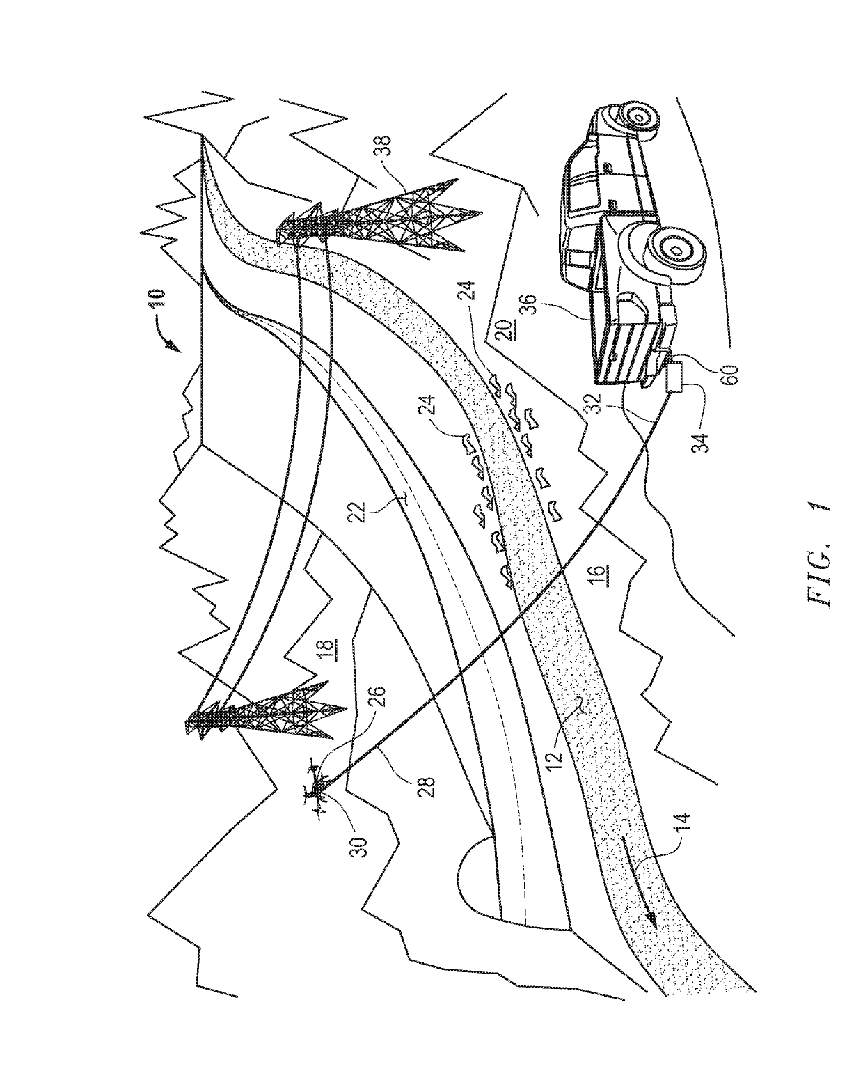
[0021]FIG. 1 depicts an example of an outdoor landscape 10 with geographical obstacles that must be considered when installing a new electrical conductor into or onto electrical power line towers, whether that conductor is part of new power line tower construction or a replacement conductor into an existing power line tower. For example, outdoor landscape 10 depicts a river 12 that flows in direction 14 through or within a valley 16. On each side of...


PUM


Abstract

An apparatus for controlling tension in a pulling rope that is attached to a flying, unmanned aerial device or drone may utilize a cylinder around which the rope is wound, a shaft that longitudinally passes through the cylinder, a disc brake rotor that is mounted to the shaft, a brake caliper that is mounted circumferentially at a periphery of the disc brake rotor, and a brake lever that tensions a cable that is attached to, and movable to control movement of, the brake caliper, which may be hydraulic, against surfaces the disc brake rotor. The brake lever may be hand actuated and mounted to a handlebar. A frame may be part of the apparatus and support apparatus components and may have a protruding hitch portion that inserts into a vehicle's receiver hitch. An adjustable pulling rope guide support through which the rope is threaded, mounts to the frame.

Description

STATEMENT REGARDING FEDERALLY SPONSORED RESEARCH OR DEVELOPMENT[0001]None.FIELD OF THE INVENTION(S)[0002]This invention relates to an apparatus and a method of tensioning an aerial rope that is attached to an unmanned aerial device, such as a drone.BACKGROUND OF THE INVENTION(S)[0003]Installing new or replacement de-energized power line conductors may be performed using a variety of known equipment and known methods depending upon the terrain over which, or through which, the power line is to be built or rebuilt. Generally, installing a conductor into its position on a power line tower or other structure involves pulling a rope or cable that is attached to a conductor to be pulled into position. In one example, in the case relatively flat, or open and generally unobstructed Earth terrain, simply pulling a conductor into place using traditional ground-based, or ground-positioned pulling equipment is possible because moving and installing pulling equipment along a generally flat right...

Claims


Application Information

Patent Timeline
Patent Type & Authority Applications(United States)
IPC IPC(8): B66D1/42B66D5/14B66D1/38H02G1/04B64C39/02
CPCB66D1/42B66D5/14B66D1/38H02G1/04B64C39/024B64C2201/12B66D1/28B64U2101/00
Inventor FULK, II, JAMES ALANLAPHAM, DAVID WENDELLNUTZ, TIMOTHY DEAN
Owner QUANTA ASSOC
Why Eureka
Try Eureka