Eureka AIR delivers breakthrough ideas for toughest innovation challenges, trusted by R&D personnel around the world.

Intelligent identification of mixed photonic lock structure and method thereof

a technology of intelligent identification and photonic locks, applied in process control, process and machine control, process control, etc., can solve the problems of ineffective reduction of manufacturing cost, complex overall structure design of optical lock structure, easy destruction and unlocking of mechanical horn locks by thieves, etc., to achieve simple overall structure, increase practicality of overall implementation, and low preparation cost

Inactive Publication Date: 2019-07-18
NAT KAOHSIUNG UNIV OF SCI & TECH +1
View PDF2 Cites 0 Cited by
  • Summary
  • Abstract
  • Description
  • Claims
  • Application Information

AI Technical Summary

Benefits of technology

[0008]In view of the above-mentioned problems, the object of the present invention is to provide a mixed photonic lock structure having intelligent identification and a use method thereof. The present invention has a simplified overall structure and relative low costs in preparation and can be widely used in different fields to achieve anti-theft effects, so the present invention has increased practical features of overall implementation.

Problems solved by technology

However, a lock core of the mechanical horn lock can be directly contacted, so the mechanical horn lock is easily destroyed and unlocked by thieves.
1. The optical lock structure needs to be connected with a power supply on the optical key and the optical lock, so the overall structure design of the optical lock structure is complicated and its manufacturing cost cannot be effectively reduced.
2. In an actual use, the optical key transmits the light source signal code to the optical lock for storage and record. However, the optical lock structure unlocks a lock also by the light key transmitting the same light source signal code to the optical lock for comparison and unlocking, so the optical lock structure is limited in use, and its anti-theft effect is also limited.

Method used


Image

  • Intelligent identification of mixed photonic lock structure and method thereof
  • Intelligent identification of mixed photonic lock structure and method thereof
  • Intelligent identification of mixed photonic lock structure and method thereof

Examples


Embodiment Construction

[0018]Hereinafter, an exemplary embodiment of the present invention will be described in detail with reference to the accompanying drawings.

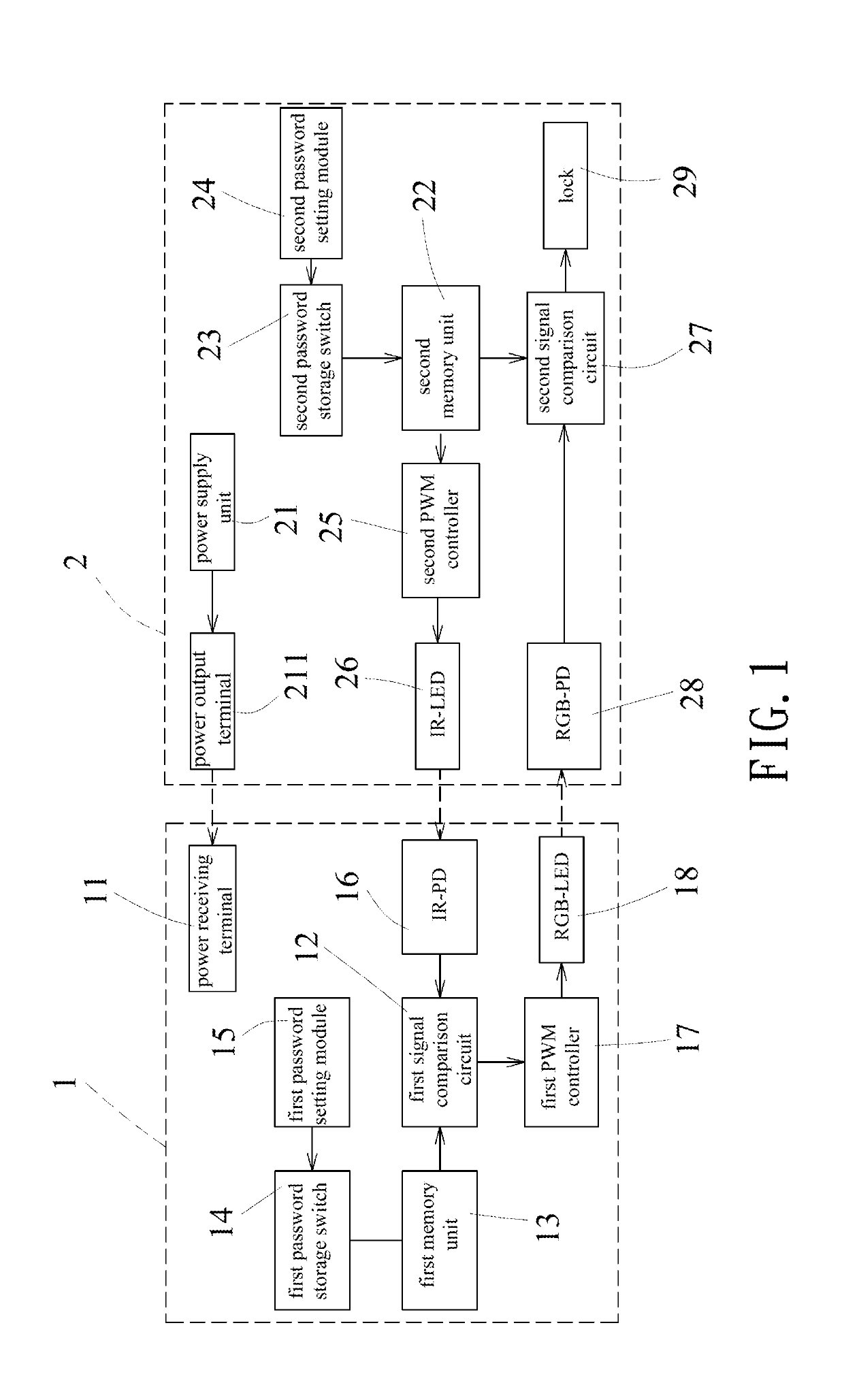
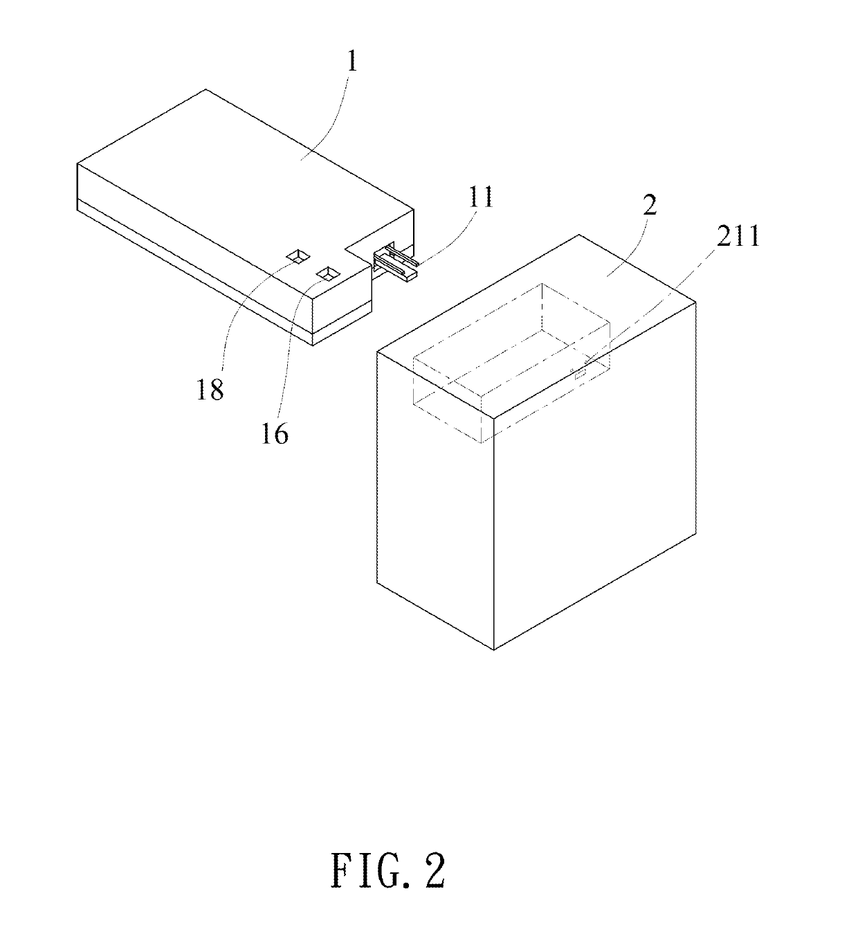
[0019]As showed in FIG. 1 and FIG. 2, a block diagram and a stereogram showing a mixed photonic lock structure having intelligent identification according to the present invention are respectively disclosed. The mixed photonic lock structure having intelligent identification mainly comprises a mixed photonic key (1) and a mixed photonic lock body (2).

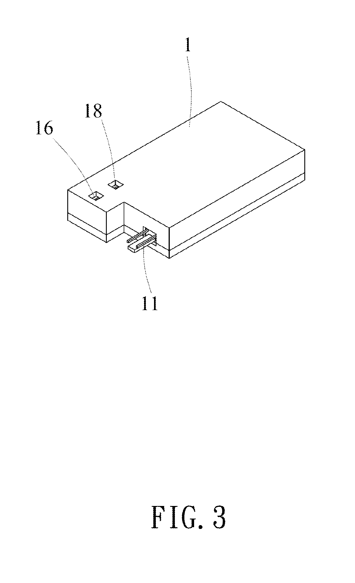
[0020]As shown in FIG. 1 to FIG. 3, the mixed photonic key (1) has a power receiving terminal (11) for receiving electric energy required by the mixed photonic key (1) from the mixed photonic lock body (2), a first signal comparison circuit (12) for comparing an input signal, a first memory unit (13) connected to the first signal comparison circuit (12), a first password storage switch (14) connected to the first memory unit (13), and a first password setting module (15) connected to the first passw...


PUM


Abstract

The invention relates to a mixed photonic lock structure having intelligent identification and a method thereof. It comprises a mixed photonic key inserted into a mixed photonic lock body. A power supply unit of the mixed photonic lock body supplies the required power to the mixed photonic lock body and the mixed photonic key. An infrared (IR)-LED in the mixed photonic lock body emits a corresponding signal to an infrared photo detector (IR-PD) in the mixed photonic key. When the comparison conducted by a signal comparison circuit of the mixed photonic key matches, a RGB-LED emits a light signal password to a RGB PD of the mixed photonic lock body to control the lock to unlock after the comparison conducted by a signal comparison circuit of the mixed photonic lock body matches.

Description

BACKGROUND OF THE INVENTION1. Field of the Invention[0001]The present invention relates to an intelligent identification of a mixed photonic lock structure and a method thereof which has a simplified overall structure and relative low costs in preparation and can be widely used in different fields to achieve anti-theft effects, so the present invention has increased practical features of overall implementation.2. Description of Related Art[0002]In daily life, constant occurrence of various criminal incidents, e.g. number of thefts, have been reported, so people usually installs a variety of locks in different kinds of articles to ensure the safety of their life and property and achieve anti-theft effects.[0003]Currently, there are a lot of locks on the market, and all kinds of locks have different characteristics to be selected for locking the different kinds of articles, e.g. mechanical horn lock, password lock, leaf lock, inductive card lock, magnet lock, and RFID sensor lock, rem...

Claims


Application Information

Patent Timeline
Patent Type & Authority Applications(United States)
IPC IPC(8): G07C9/00H05B33/08G01J1/44E05B47/00H05B44/00
CPCG07C9/00571E05B47/0001G01J1/44H05B33/0803E05B49/006G07C9/00309G07C2009/00603G07C2009/00785G07C2009/00642G07C9/00857G07C9/00817H05B45/325H05B47/16G07C9/00174G05B19/00
Inventor YANG, CHI-TASHIEH, YUN-SOWWANG, ZIH-RUEIWANG, DING-YUANLIU, CHIH-TINGCHANG, JUN-XIANGZHANG, XUAN-ZHILIN, PO-JUXU ZENG, GUO-WEI
Owner NAT KAOHSIUNG UNIV OF SCI & TECH
Why Eureka
Eureka Blog
Learn More