Power storage device
- Summary
- Abstract
- Description
- Claims
- Application Information
AI Technical Summary
Benefits of technology
Problems solved by technology
Method used
Image

Examples
first embodiment
[0036](First Embodiment)
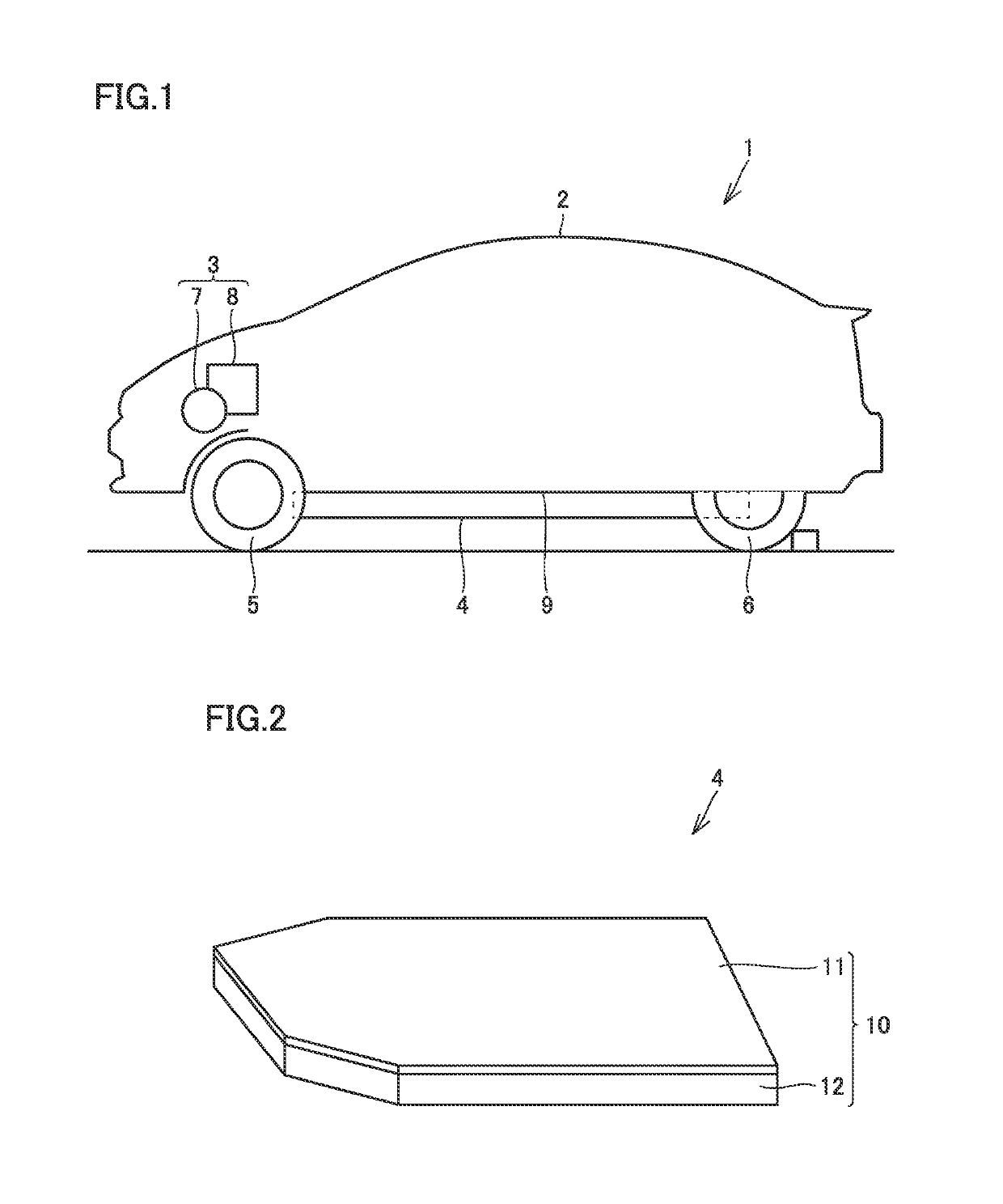
[0037]FIG. 1 is a side view schematically showing a vehicle 1. Vehicle 1 includes a vehicle body 2, a drive device 3, a power storage device 4, front wheels 5, and rear wheels 6.
[0038]In vehicle body 2, an engine compartment, a riding space, and a luggage compartment are formed. The engine compartment is formed on the front side of vehicle 1, and the riding space is formed behind the engine compartment. The luggage compartment is formed behind the riding space.
[0039]Drive device 3 is accommodated within the engine compartment. Drive device 3 includes a rotating electrical machine 7 and a PCU (Power Control Unit) 8. PCU 8 includes an inverter and a converter. PCU 8 is electrically connected to power storage device 4 and rotating electrical machine 7.
[0040]PCU 8 boosts a voltage of direct current (DC) power supplied from power storage device 4, and further converts the DC power into alternating current (AC) power and supplies it to rotating electrical machine 7...
second embodiment
[0070](Second Embodiment)
[0071]A power storage device 4A in accordance with a second embodiment will be described using FIG. 7 and the like. FIG. 7 is a side view schematically showing power storage device 4A. Power storage device 4A includes power storage module 15 and a temperature increasing unit 20A. Power storage module 15 is configured as in the first embodiment described above.
[0072]Temperature increasing unit 20A includes elastic members 36A, 36B, a placement stand 42, heater 35 and insulating plate 37. Heater 35 and placement stand 42 are formed to be elongated in a direction in which power storage module 15 extends.
[0073]FIG. 8 is a perspective view showing heater 35, placement stand 42, and the like, and FIG. 9 is a cross sectional view showing heater 35, placement stand 42, and the like.
[0074]Elastic member 36A and elastic member 36B are arranged to be spaced from each other in front-back direction D of vehicle 1. Elastic members 36A, 36B are formed to be elongated in wi...
third embodiment
[0090](Third Embodiment)
[0091]A power storage device 4B in accordance with a third embodiment will be described using FIG. 11. It should be noted that FIG. 11 is a side cross sectional view schematically showing power storage device 4B. The configuration of power storage device 4B in accordance with the third embodiment is different from the configuration of power storage device 4 in accordance with the first embodiment in terms of the elastic member, and the components other than the elastic member of power storage device 4B are identical or substantially identical to the components of power storage device 4. Accordingly, the configuration of an elastic member 36C of power storage device 4B will be mainly described.
[0092]Elastic member 36C includes a plurality of elastic portions 60, 61, and 62. Elastic portion 61 is provided at a position closer to the central portion of power storage module 15 in width direction W than elastic portion 60 and elastic portion 62. In the example sho...
PUM
 Abstract
Description
Claims
Application Information
 - Generate Ideas
- Intellectual Property
- Life Sciences
- Materials
- Tech Scout
- Unparalleled Data Quality
- Higher Quality Content
- 60% Fewer Hallucinations
Browse by: Latest US Patents, China's latest patents, Technical Efficacy Thesaurus, Application Domain, Technology Topic, Popular Technical Reports.
© 2025 PatSnap. All rights reserved.Legal|Privacy policy|Modern Slavery Act Transparency Statement|Sitemap|About US| Contact US: help@patsnap.com