Tool on a tool carrier for tilling and comminuting

Active Publication Date: 2019-07-25
SEPPI M
View PDF0 Cites 2 Cited by
  • Summary
  • Abstract
  • Description
  • Claims
  • Application Information

AI Technical Summary

Benefits of technology

This invention aims to provide a tool holder that can be used for an extended period of time without experiencing excessive wear and tear. To achieve this, the tool is securely held in place using a clamp and bolt, which prevents the tool from moving in its cutting direction. As a result, the tool is less exposed to wear and tear, which reduces the need for maintenance and downtime.

Problems solved by technology

By this arrangement, the tool is not able to move in the cutting direction.

Method used


Image

  • Tool on a tool carrier for tilling and comminuting
  • Tool on a tool carrier for tilling and comminuting
  • Tool on a tool carrier for tilling and comminuting

Examples


Embodiment Construction

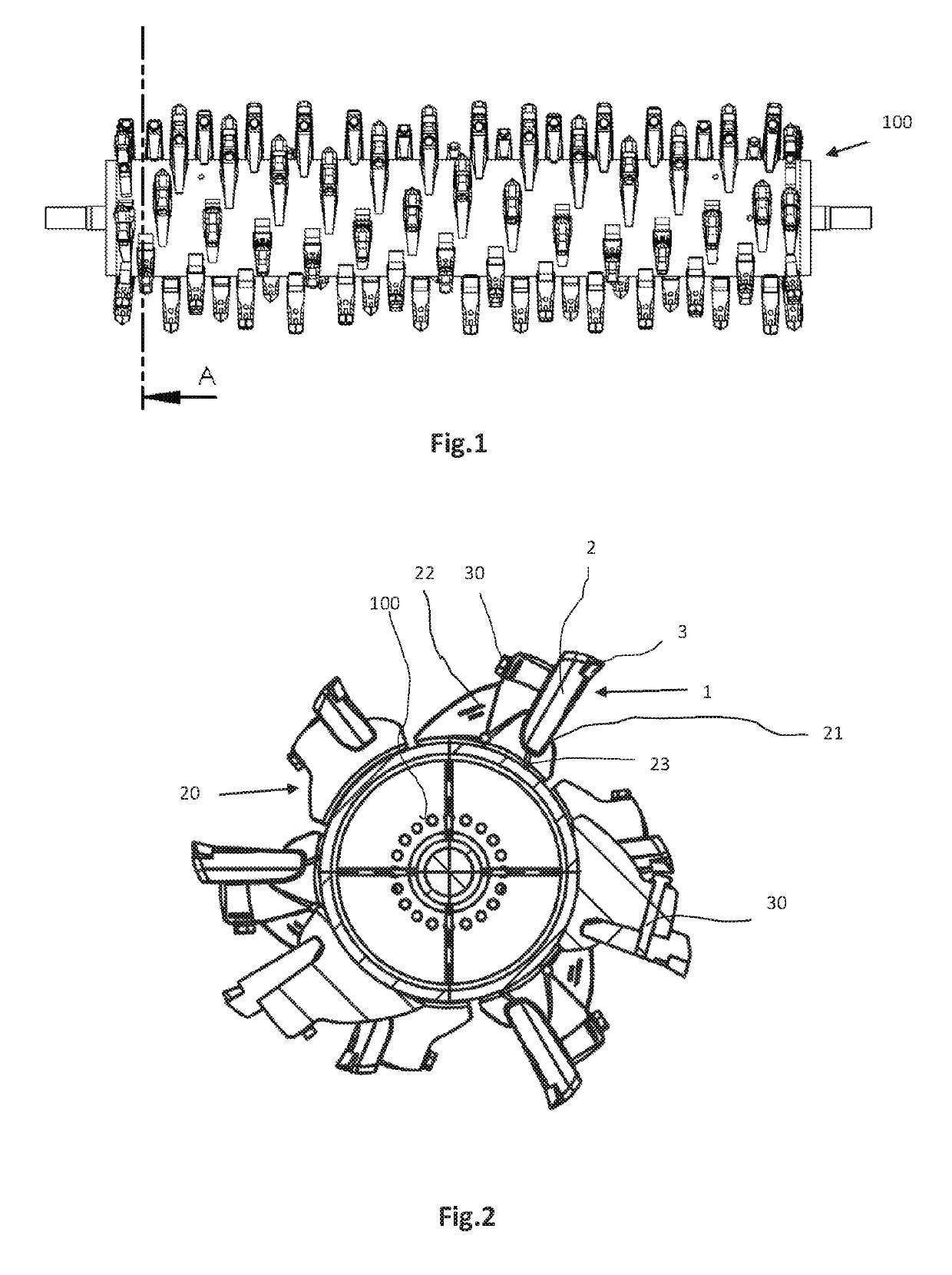
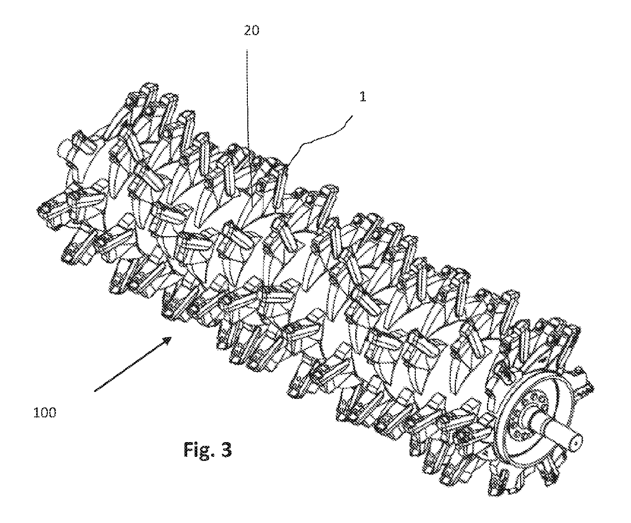
[0022]In FIG. 1 a tool-holder rotor is designated by numeral 100. Tool holders 20 are arranged on the tool-holder rotor 1. Each tool holder 20 forms a seat for a tool 1. The tool holder 20 is composed of a front portion 21 in the working direction, a lower portion 23 and a rear portion 22 including a through hole for a bolt 30.

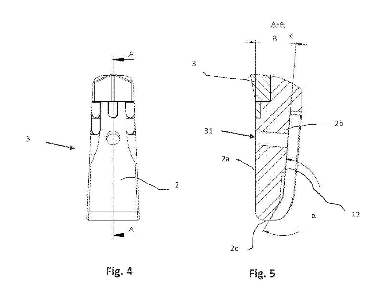
[0023]The tool 1 for grinders, mulchers and the like, is arranged in a tool holder 20 for a tool-holder rotor 100 rotating about the axis of the rotor. This tool 1 is received in a seat of the tool holder 20 on the tool-holder rotor 100. The tool holder 20 is formed by a front portion 21 disposed in the cutting direction and a rear portion 22 upon which the tool is fastened with its surface that faces away from the cutting direction. The tool 1 has a body 2 with a front surface 2a oriented in the direction of rotation of the rotor, and a rear surface 2b that faces away from the front surface 2a.

[0024]According to the invention, the rear surface 2b is inclined...


PUM


Abstract

A tool for tilling and comminuting in a tool carrier with rotor which is rotatable about the rotor axis, the tool is received in a receptacle of the tool carrier arranged on the rotor. The receptacle is formed by a first face provided in the cutting direction and second face on which the tool is fastened by means of its face which faces away from the cutting direction, the tool has a body which has an end face in the direction of rotation of the rotor and a rear face opposite the end face. The rear face is inclined by 1° to 10° with respect to the end face and the tool is braced and held between the face in the cutting direction of the receptacle and the face of the receptacle that faces away from the cutting direction, play is left between the tool and receptacle base.

Description

BACKGROUND OF THE INVENTION[0001]The present invention relates to a tool located in a tool holder.[0002]Such tools are exposed to a high wear and stresses that might eventually break and deform the tool.[0003]Generally, two types of tool holders for mulchers and / or grinders are known. The first type has a bearing surface upon which the tool is fastened with its surface that faces away from the cutting direction, for example by means of a bolt. This type of tool holder is known, for example, from DE 2013 110289 A1. This type of tool holder has the drawback that the tool is exposed with his entire body to impacts and damage in the cutting direction.[0004]A second type of tool holder has a seat for receiving the tool, which is formed by a first surface disposed in the cutting direction and a second surface upon which the tool is fastened with its surface that faces away from the cutting direction. A tool holder of this type is known, for example, from EP 1,693,110. With this type of se...

Claims


Application Information

Patent Timeline
IPC IPC(8): A01B33/10B02C13/06B02C18/18
CPCA01B33/103B02C13/06B02C18/18A01B33/10
Inventor SEPPI, LORENZ
Owner SEPPI M
Why Eureka
Try Eureka