Optical probes with correction components for astigmatism correction

a technology of optical probes and components, applied in the field of optical probes, can solve the problems of reducing the image quality of the optical system, the optical system of optical imaging catheters or endoscopes is usually fragile,

Active Publication Date: 2019-07-25
CANON USA
View PDF0 Cites 7 Cited by
  • Summary
  • Abstract
  • Description
  • Claims
  • Application Information

AI Technical Summary

Problems solved by technology

An optical-imaging catheter or endoscope's optical system is usually fragile and is theref

Method used


Image

  • Optical probes with correction components for astigmatism correction
  • Optical probes with correction components for astigmatism correction
  • Optical probes with correction components for astigmatism correction

Examples


Embodiment Construction

[0030]The following paragraphs describe certain explanatory embodiments. Other embodiments may include alternatives, equivalents, and modifications. Additionally, the explanatory embodiments may include several novel features, and a particular feature may not be essential to some embodiments of the devices, systems, and methods that are described herein.

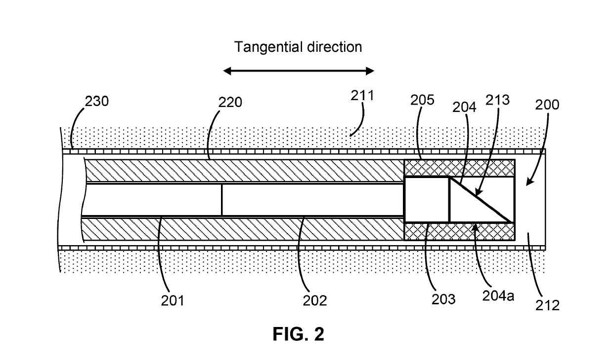
[0031]Some optical-imaging devices (e.g., endoscopes) are configured to capture images from inside a subject, such as a human patient. These optical-imaging devices may include an optical probe, and the optical probe may include both a lens and a reflecting surface at a distal tip. The lens and the reflecting surface focus a beam of light, collect the beam of light, and guide the beam of light. Also, one or more optical fibers in the fiber probe can be used to navigate the optical probe to a sample (e.g., organs, tissues), deliver light to the sample, and detect light that is reflected by the sample. Furthermore, an optical-imaging d...


PUM


Abstract

An optical probe comprises a light-guiding component, an optical component, a light-reflecting component that is configured to receive light from the optical component and direct the light along a path, and a correction component. The correction component lies in the path, the correction component has an optical power, and the correction component has a center of curvature that substantially coincides with an optical axis of the optical component.

Description

BACKGROUND[0001]This application generally concerns optical probes.[0002]An optical-imaging catheter or endoscope's optical system is usually fragile and is therefore protected by a sheath. Astigmatism is created in the optical system by the cylindrical shape of the sheath. Astigmatism causes the foci of the beams of light in two orthogonal directions to converge at different distances with different beam sizes or to diverge in one direction while converging in another direction. This astigmatism reduces the image quality of the optical system.SUMMARY[0003]Some embodiments of an optical probe comprise a light-guiding component, an optical component, a light-reflecting surface that is configured to receive light from the optical component and direct the light along a path, and a correction component. Also, the correction component lies in the path, the correction component has an optical power, and the correction component has a center of curvature that substantially coincides with a...

Claims


Application Information

Patent Timeline
IPC IPC(8): A61B1/00A61B5/00A61B1/07
CPCA61B1/00188A61B1/00096A61B5/0084A61B1/07A61B5/0066A61B5/0035A61B5/0071A61B1/00177G02B23/243G02B23/2423
Inventor WU, TZU-YU
Owner CANON USA
Why Eureka
Try Eureka