
Cleaning robot system and operating method thereof

a cleaning robot and robot technology, applied in the field of robot systems and an operating method thereof, can solve the problems of increasing the working time, unable to continuously carry out cleaning operations, and the battery of the cleaning robot requires long-term endurance, and achieves automatic replacement of the battery in rapid, good working performance.

Inactive Publication Date: 2019-08-01
LITE ON ELECTRONICS (GUANGZHOU) LTD +1
View PDF14 Cites 10 Cited by
  • Summary
  • Abstract
  • Description
  • Claims
  • Application Information

AI Technical Summary

Benefits of technology

The cleaning robot system described in this patent is designed to automatically replace batteries quickly and efficiently. It includes multiple batteries and electromagnets that magnetically attach the batteries to the robot, allowing it to carry all or some of the batteries. When the robot carries all of the batteries, it can perform a high power-consuming cleaning task or extend its working time. When the robot carries only a portion of the batteries, it can easily return to a charging dock to replace the battery and continue cleaning. This design improves the robot's working efficiency and allows it to be positioned stably without the need for a wall-fixed charging dock.

Problems solved by technology

However, as functions of the cleaning robots are gradually increased and application ranges thereof are no longer limited to household use, batteries for the cleaning robots require long-term endurance.
The conventional cleaning robot must return and stay at a charging station at regular intervals to wait for the battery to be charged, and is unable to continuously carry out cleaning operations.
Therefore, a cleaning robot system that may quickly and automatically replace the battery without waiting for a charging time and may increase a working time is an urgent product required in the field.
When the cleaning robot carries all of the batteries, a high power-consuming cleaning task is adapted to be carried out or a working time is adapted to be prolonged.

Method used


Image

  • Cleaning robot system and operating method thereof
  • Cleaning robot system and operating method thereof
  • Cleaning robot system and operating method thereof

Examples


Embodiment Construction

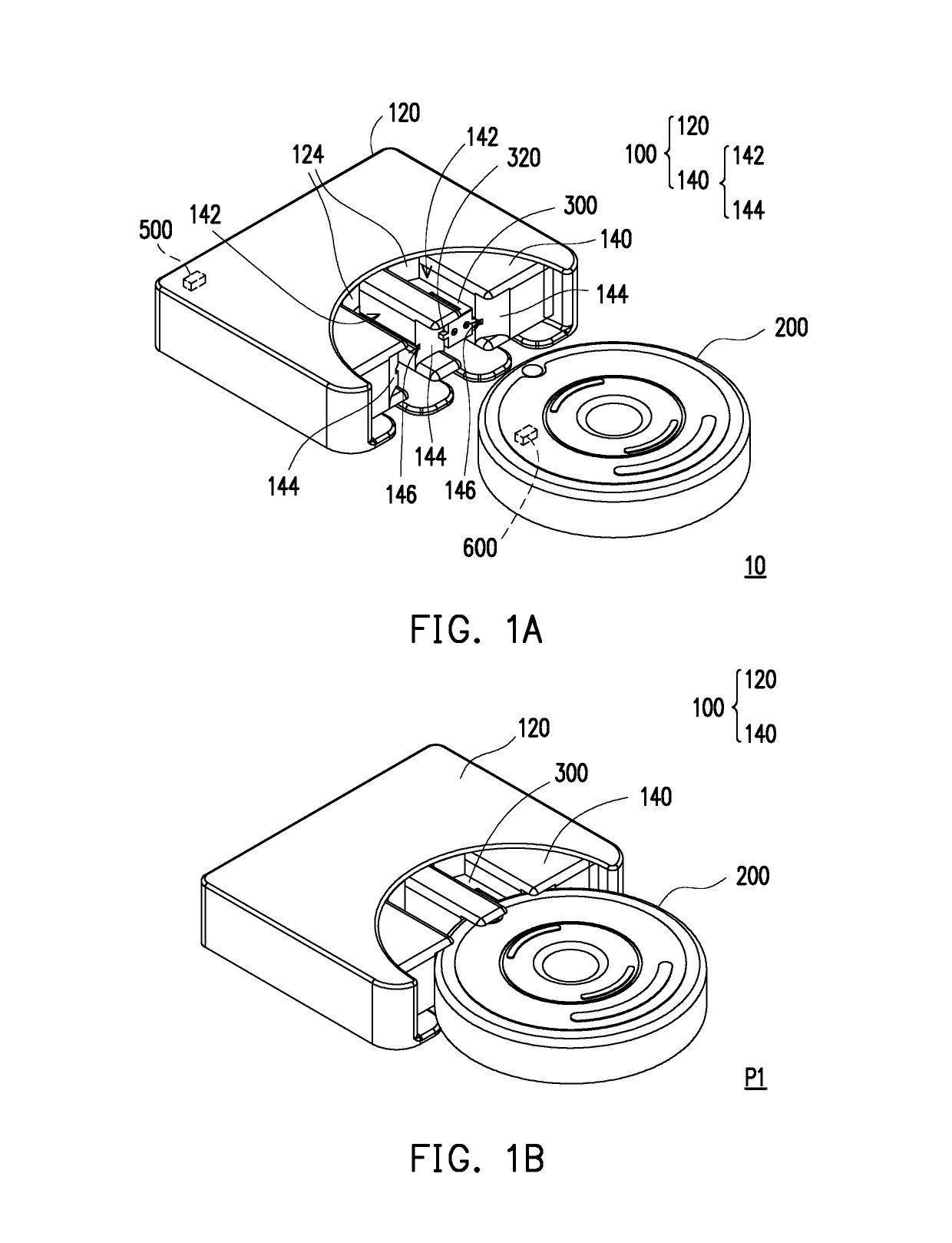
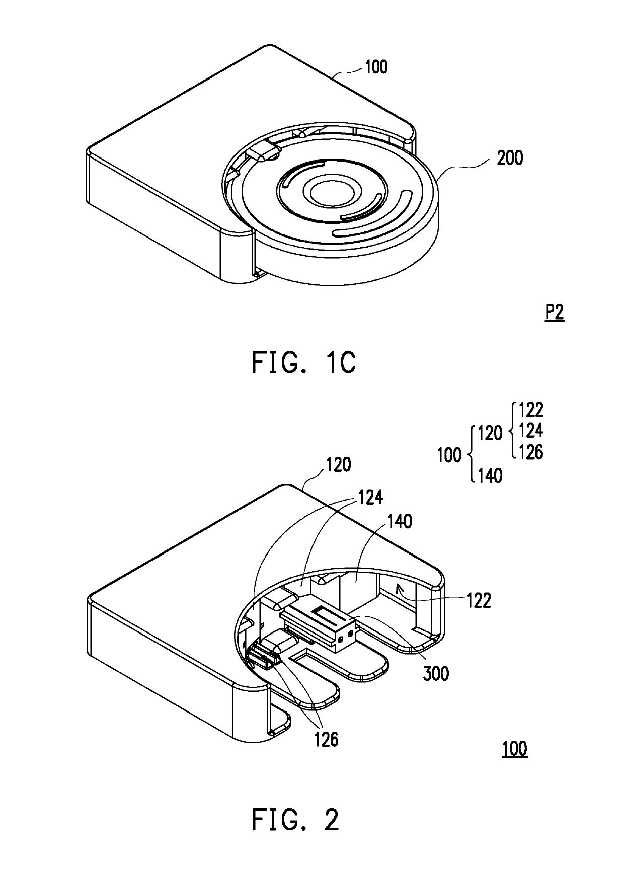
[0023]FIG. 1A is a three-dimensional view of a cleaning robot system according to an embodiment of the disclosure. FIG. 1B is a three-dimensional view of a cleaning robot of FIG. 1A located at a first position. FIG. 1C is a three-dimensional view of the cleaning robot of FIG. 1A located at a second position. Referring to FIG. 1A, FIG. 1B, and FIG. 1C, the cleaning robot system 10 includes a charging dock 100, a cleaning robot 200, and a plurality of batteries 300. In the embodiment, the cleaning robot 200 is, for example, a sweeping robot, a mopping robot, or other types of the cleaning robot. The charging dock 100 includes a fixed base 120 and a stretchable base 140. The stretchable base 140 is connected to the fixed base 120 in a stretchable manner. In the embodiment, the cleaning robot 200 is adapted to move to the charging dock 100 and to be electrically connected to the charging dock 100. When the cleaning robot 200 approaches the charging dock 100, the cleaning robot 200 may m...


PUM


Abstract

A cleaning robot system includes a cleaning robot and a charging dock. The cleaning robot carries a first battery. The charging dock magnetically attracts a second battery and charges the second battery. When the cleaning robot is electrically connected to the charging dock and an electrical quantity of the first battery is lower than a default electrical quantity, the charging dock magnetically attracts the first battery and releases the second battery and the cleaning robot carries the second battery.

Description

CROSS-REFERENCE TO RELATED APPLICATION[0001]This application claims the priority benefit of China application serial no. 201810096405.8, filed on Jan. 31, 2018. The entirety of the above-mentioned patent application is hereby incorporated by reference herein and made a part of this specification.BACKGROUNDTechnical Field[0002]The disclosure relates to a robot system and an operating method thereof, and particularly relates to a cleaning robot system and an operating method thereofDescription of Related Art[0003]Presently, development of robots gradually draws attention, and the field of robots includes cleaning robots for cleaning environments. However, as functions of the cleaning robots are gradually increased and application ranges thereof are no longer limited to household use, batteries for the cleaning robots require long-term endurance. The conventional cleaning robot must return and stay at a charging station at regular intervals to wait for the battery to be charged, and is...

Claims


Application Information

Patent Timeline
Patent Type & Authority Applications(United States)
IPC IPC(8): A47L9/28A47L11/40
CPCA47L9/2873A47L9/2884A47L11/4005A47L11/4011A47L2201/022
Inventor LU, TIEN-SHENGWU, YU-CHUNG
Owner LITE ON ELECTRONICS (GUANGZHOU) LTD
Learn More