Coil component and electronic device
- Summary
- Abstract
- Description
- Claims
- Application Information
AI Technical Summary
Benefits of technology
Problems solved by technology
Method used
Image

Examples
Example
EXAMPLE 1
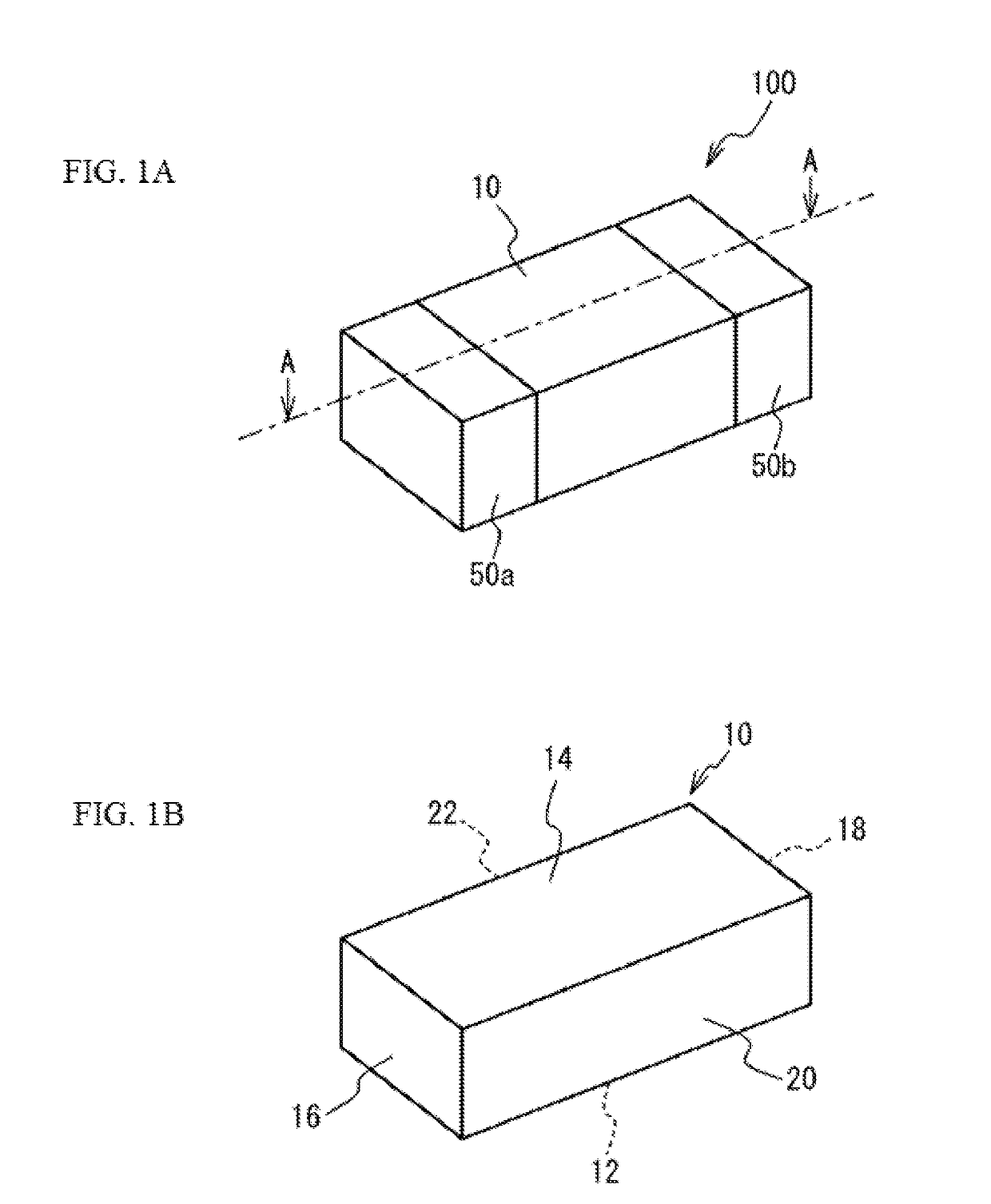
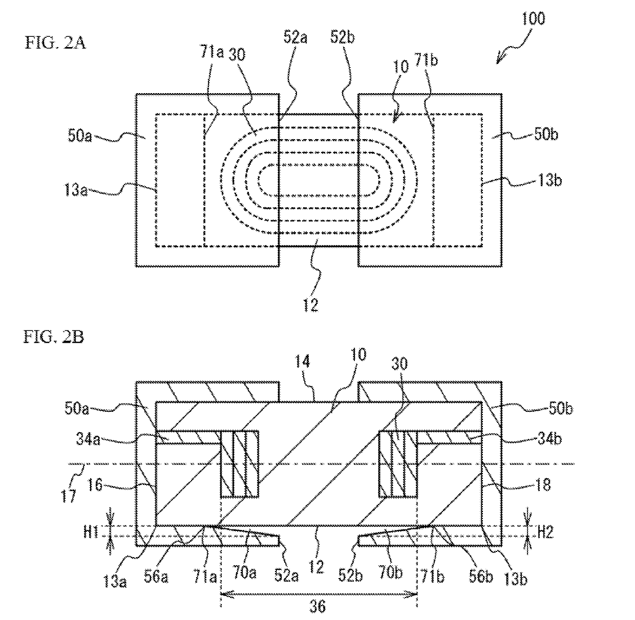
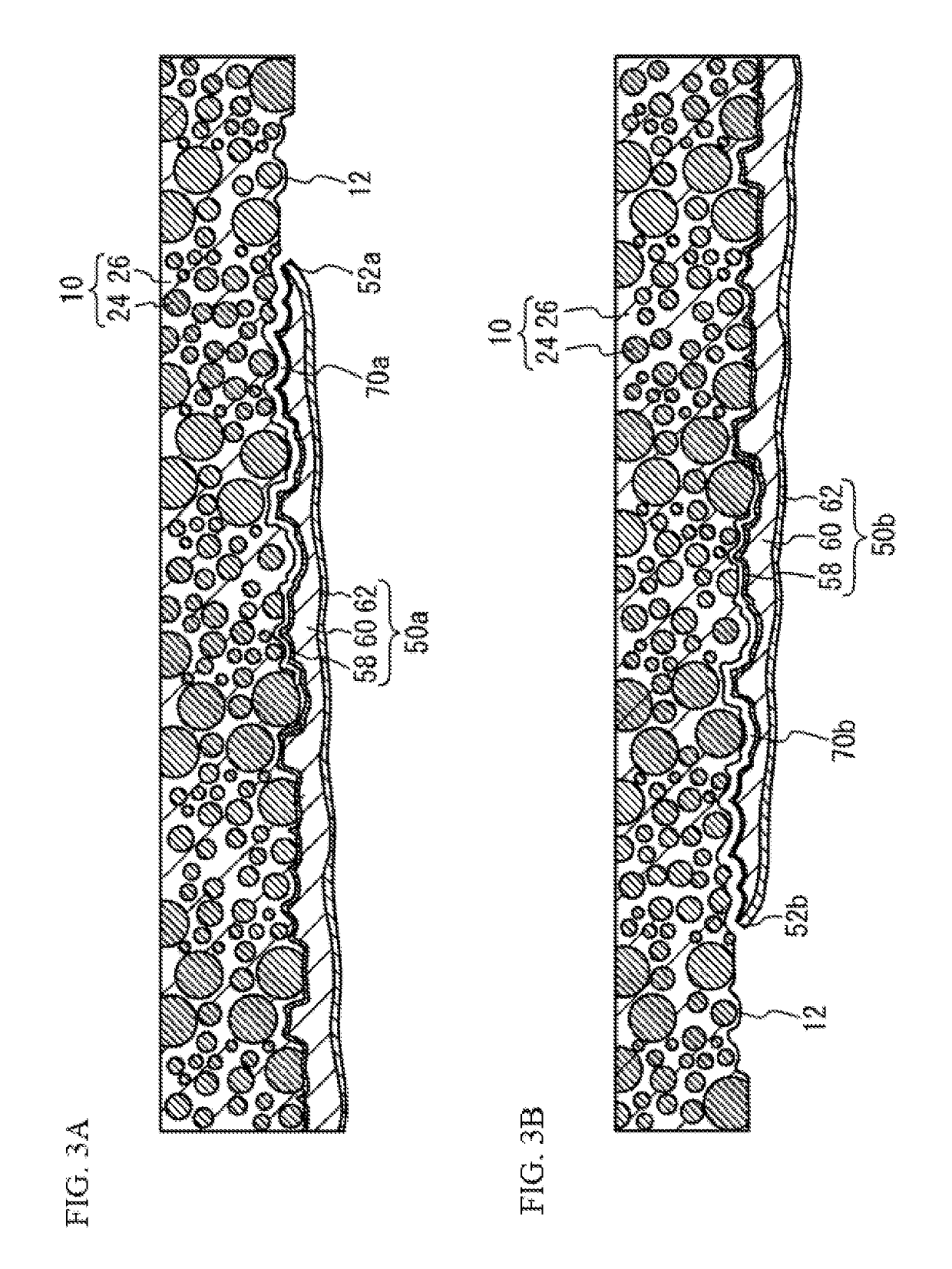
[0061]FIG. 1A is a perspective view of the coil component, while FIG. 1B is a perspective view of the element body part, pertaining to Example 1. FIG. 2A is a bottom view of the coil component pertaining to Example 1, while FIG. 2B is a view of cross-section A-A in FIG. 1A. FIGS. 3A and 3B are each an enlarged cross-sectional view around a tip part of an external electrode. As shown in FIGS. 1A, 1B, 2A, 2B, 3A, and 3B, the coil component 100 in Example 1 comprises an element body part 10, a coil 30 built into the element body part 10, lead conductors 34a, 34b led out from the coil 30, and external electrodes 50a, 50b connected to the lead conductors 34a, 34b.
[0062]The element body part 10 is shaped as a rectangular solid having a bottom face 12, a top face 14, a pair of end faces 16, 18, and a pair of side faces 20, 22. The bottom face 12 is a mounting face, while the top face 14 is a face opposite the bottom face 12. The end faces 16, 18 are faces connected to the short s...
Example
EXAMPLE 2
[0083]FIG. 6A is a top view, FIG. 6B is a bottom view, and FIG. 6C is a cross-sectional view, of the coil component pertaining to Example 2. As shown in FIGS. 6A to 6C, the coil component 200 in Example 2 has a void 72a formed on the top face 14 of the element body part 10 between the element body part 10 and the external electrode 50a, in a manner extending from the tip part 54a of the external electrode 50a. Similarly, a void 72b is formed on the top face 14 of the element body part 10 between the element body part 10 and the external electrode 50b, in a manner extending from the tip part 54b of the external electrode 50b. In other words, the void 72a is open on the tip part 54a side of the external electrode 50a, while the void 72b is open on the tip part 54b side of the external electrode 50b. The tip part 54a of the external electrode 50a, and the tip part 54b of the external electrode 50b, are where the external electrodes 50a, 50b face each other on the top face 14 o...
Example
EXAMPLE 3
[0086]FIG. 7 is a cross-sectional view of the coil component pertaining to Example 3. As shown in FIG. 7, the coil component 300 in Example 3 has its lead conductors 34a, 34b led out from the coil 30 toward the bottom face 12 of the element body part 10, and connected to the external electrodes 50a, 50b on the bottom face 12 of the element body part 10. The remaining constitutions are the same as those in Example 1 and therefore not explained.
[0087]Examples 1 and 2 present examples where the lead conductor 34a is led out from the coil 30 toward the end face 16 of the element body part 10, while the lead conductor 34b is led out from the coil 30 toward the end face 18 of the element body part 10. However, this is not the only case and, as shown in Example 3, the lead conductors 34a, 34b may be led out from the coil 30 toward the bottom face 12 of the element body part 10. In this case, preferably voids 70a, 70b are not formed in the part where the lead conductor 34a is expos...
PUM
 Abstract
Description
Claims
Application Information
 - R&D Engineer
- R&D Manager
- IP Professional
- Industry Leading Data Capabilities
- Powerful AI technology
- Patent DNA Extraction
Browse by: Latest US Patents, China's latest patents, Technical Efficacy Thesaurus, Application Domain, Technology Topic.
© 2024 PatSnap. All rights reserved.Legal|Privacy policy|Modern Slavery Act Transparency Statement|Sitemap