3D semiconductor device

a technology of integrated circuits and semiconductors, applied in the field of integrated circuit devices and fabrication methods, can solve the problems of increasing the cost of product development, etc., to achieve dominating ic performance and power, reducing the impact of inter-chip interconnects, and large size

Active Publication Date: 2019-08-01
MONOLITHIC 3D
View PDF11 Cites 10 Cited by
  • Summary
  • Abstract
  • Description
  • Claims
  • Application Information

AI Technical Summary

Benefits of technology

[0019]Additionally there is a growing need to reduce the impact of inter-chip interconnects. In fact, interconnects are now dominating IC performance and power. One solution to shorten interconnect may be to use a 3D IC. Currently, the only known way for general logic 3D IC is to integrate finished device one on top of the other by utilizing Through-Silicon-Vias as now called TSVs. The problem with TSVs is that their large size, usually a few microns each, may severely limit the number of connections that can be made. Some embodiments of the current invention may provide multiple alternatives to constructing a 3D IC wherein many connections may be made less than one micron in size, thus enabling the use of 3D IC technology for most device applications.

Problems solved by technology

Semiconductor manufacturing is known to improve device density in an exponential manner over time, but such improvements come with a price.
The mask set cost required for each new process technology has also been increasing exponentially.
These changes represent an increasing challenge primarily to custom products, which tend to target smaller volume and less diverse markets therefore making the increased cost of product development very hard to accommodate.
However, wires (interconnects) that connect together transistors degrade in performance with “scaling”.
The problem with TSVs is that they are relatively large (a few microns each in area) and therefore may lead to highly limited vertical connectivity.
The problem with TSVs is that their large size, usually a few microns each, may severely limit the number of connections that can be made.

Method used


Image

  • 3D semiconductor device
  • 3D semiconductor device
  • 3D semiconductor device

Examples


Embodiment Construction

[0054]Embodiments of the present invention are now described with reference to the drawing figures. Persons of ordinary skill in the art will appreciate that the description and figures illustrate rather than limit the invention and that in general the figures are not drawn to scale for clarity of presentation. Such skilled persons will also realize that many more embodiments are possible by applying the inventive principles contained herein and that such embodiments fall within the scope of the invention which is not to be limited except by the appended claims.

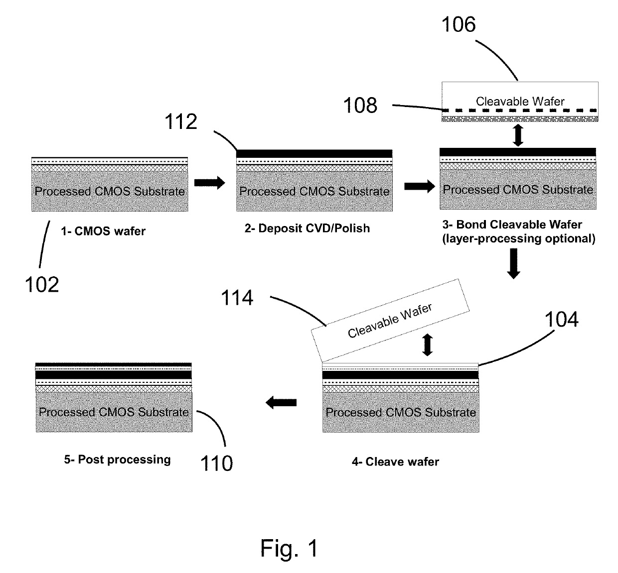
[0055]Some drawing figures may describe process flows for fabricating devices. The process flows, which may be a sequence of steps for fabricating a device, may have many structures, numerals and labels that may be common between two or more successive steps. In such cases, some labels, numerals and structures used for a certain step's figure may have been described in the previous steps' figures.

[0056]A technology for creati...


PUM

PropertyMeasurementUnit
sizeaaaaaaaaaa
thickaaaaaaaaaa
temperatureaaaaaaaaaa

Abstract

A 3D semiconductor device including: a first die, comprising a first die area and a plurality of first die top contacts; a second die, comprising a second die area and a plurality of first bottom contacts; and a third die, comprising a third die area and a plurality of second bottom contacts, wherein said first die area is greater than the sum of said second die area and said third die area, wherein said second die and said third die are both placed on top of said first die laterally with respect to each other, wherein said plurality of first bottom contacts are connected to said first die top contacts, and wherein said plurality of second bottom contacts are connected to said first die top contacts.

Description

CROSS-REFERENCE OF RELATED APPLICATIONS[0001]This application is a continuation-in-part of co-pending U.S. patent application Ser. No. 15 / 922,913 filed Mar. 16, 2018, which is a continuation-in-part of U.S. patent application Ser. No. 15 / 409,740 filed Jan. 19, 2017, (now issued as U.S. Pat. No. 9,941,332 on Apr. 10, 2018), which is a continuation-in-part of U.S. patent application Ser. No. 15 / 224,929 filed Aug. 1, 2016 (now issued as U.S. Pat. No. 9,853,089 on Dec. 26, 2017), which is a continuation-in-part of U.S. patent application Ser. No. 14 / 514,386 filed Oct. 15, 2014 (now issued as U.S. Pat. No. 9,406,670 on Aug. 2, 2016), which is a continuation of U.S. patent application Ser. No. 13 / 492,382 filed Jun. 8, 2012 (now issued as U.S. Pat. No. 8,907,442 on Dec. 9, 2014), which is a continuation of U.S. patent application Ser. No. 13 / 246,384 filed Sep. 27, 2011 (now issued as U.S. Pat. No. 8,237,228 on Aug. 7, 2012), which is a continuation U.S. patent application Ser. No. 12 / 900,3...

Claims


Application Information

Patent Timeline
Patent Type & Authority Applications(United States)
IPC IPC(8): H01L27/06H01L29/812H01L29/808H01L27/092H01L29/732H01L29/66H01L21/8238H01L21/768H01L29/786H01L29/45H01L29/423H01L23/367H01L27/12H01L27/118H01L27/11578H01L27/11551H01L27/112H01L27/11H01L27/108H01L27/105H01L27/02H01L23/544H01L23/48H01L21/84H01L21/822H01L21/762G03F9/00H01L23/532H01L23/528H01L23/522
CPCH01L27/0688H01L29/812H01L29/808H01L27/092H01L29/732H01L29/66848H01L21/823871H01L21/76898H01L29/78645H01L29/78642H01L29/78639H01L29/66901H01L29/66621H01L29/66272H01L29/458H01L29/42392H01L23/367H01L27/1203H01L27/11898H01L27/11807H01L27/11578H01L27/11551H01L27/112H01L27/1108H01L27/11H01L27/10897H01L27/10894H01L27/10876H01L27/105H01L27/0207H01L23/544H01L23/481H01L21/84H01L21/8221H01L21/76254G03F9/7084G03F9/7076H01L23/53228H01L23/53214H01L23/528H01L23/5226H01L29/66545H01L2924/181H01L24/73H01L2224/45147H01L2924/1305H01L2924/14H01L2924/13062H01L2924/1301H01L2924/13091H01L2924/00011H01L2924/12032H01L2924/3025H01L2224/45124H01L2924/15311H01L2224/73265H01L2224/73204H01L2224/48227H01L2224/48091H01L2224/32225H01L2224/32145H01L2224/16225H01L2224/16145H01L2924/10253H01L27/088H01L2924/3011H01L2223/54453H01L2223/54426H01L2223/5442H01L2224/73253H01L21/268H01L29/786H01L23/3171H01L25/0657H01L23/3677H10B63/845H10N70/823H10N70/20H10B41/35H10B41/27H10B43/35H10B43/20H01L2924/00H10B10/00H10B10/125H10B12/09H10B12/50H10B12/053H10B20/00H10B41/20
Inventor OR-BACH, ZVIWURMAN, ZEEV
Owner MONOLITHIC 3D
Why Eureka
Try Eureka