Ceiling fitting with a lighting module

a technology of lighting module and ceiling fitting, which is applied in the direction of lighting and heating apparatus, coupling device connection, lighting support device, etc., can solve the problems of increasing the cost, and achieve the effect of reducing the cost of replacement and maintenance, easy and convenient disassembly, and easy and quick removal from the canopy

Active Publication Date: 2019-08-08
DONG GUAN BRIGHT YIN HUEY LIGHTING
View PDF0 Cites 1 Cited by
  • Summary
  • Abstract
  • Description
  • Claims
  • Application Information

AI Technical Summary

Benefits of technology

[0004]According to the primary advantage of the present invention, the lighting module and the canopy are replaced individually, thereby decreasing the cost of replacement and maintenance.
[0005]According to another advantage of the present invention, the user only needs to press the movable hook to detach the lamp board from the movable hook so as to remove the lighting module from the canopy, so that the lighting module and the canopy are assembled and disassembled easily and conveniently.
[0006]According to a further advantage of the present invention, the lighting modu...

Problems solved by technology

However, the light source and the canopy are combined integrally and cannot be replaced or repaired individually, so that i...

Method used


Image

  • Ceiling fitting with a lighting module
  • Ceiling fitting with a lighting module
  • Ceiling fitting with a lighting module

Examples


Embodiment Construction

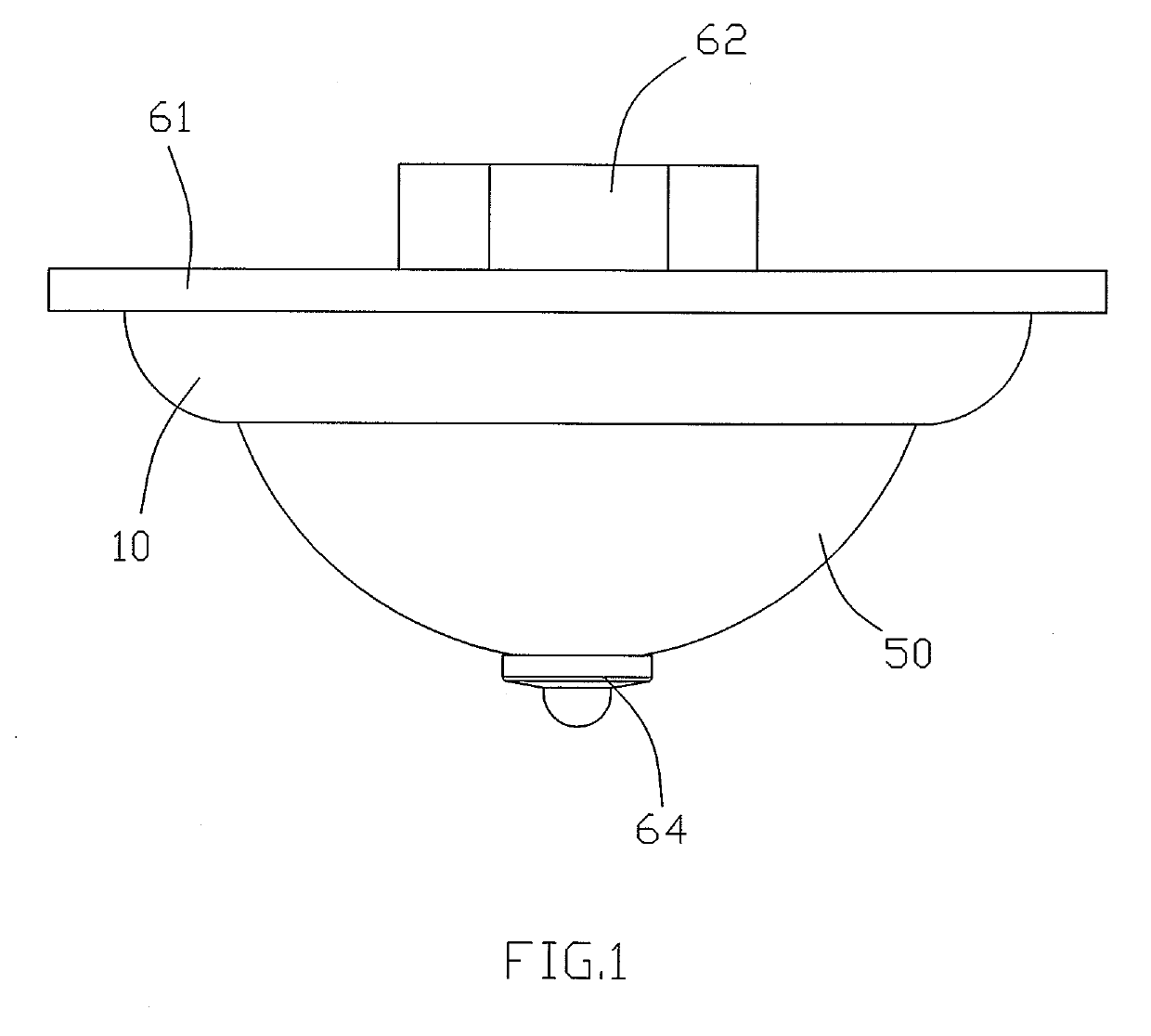
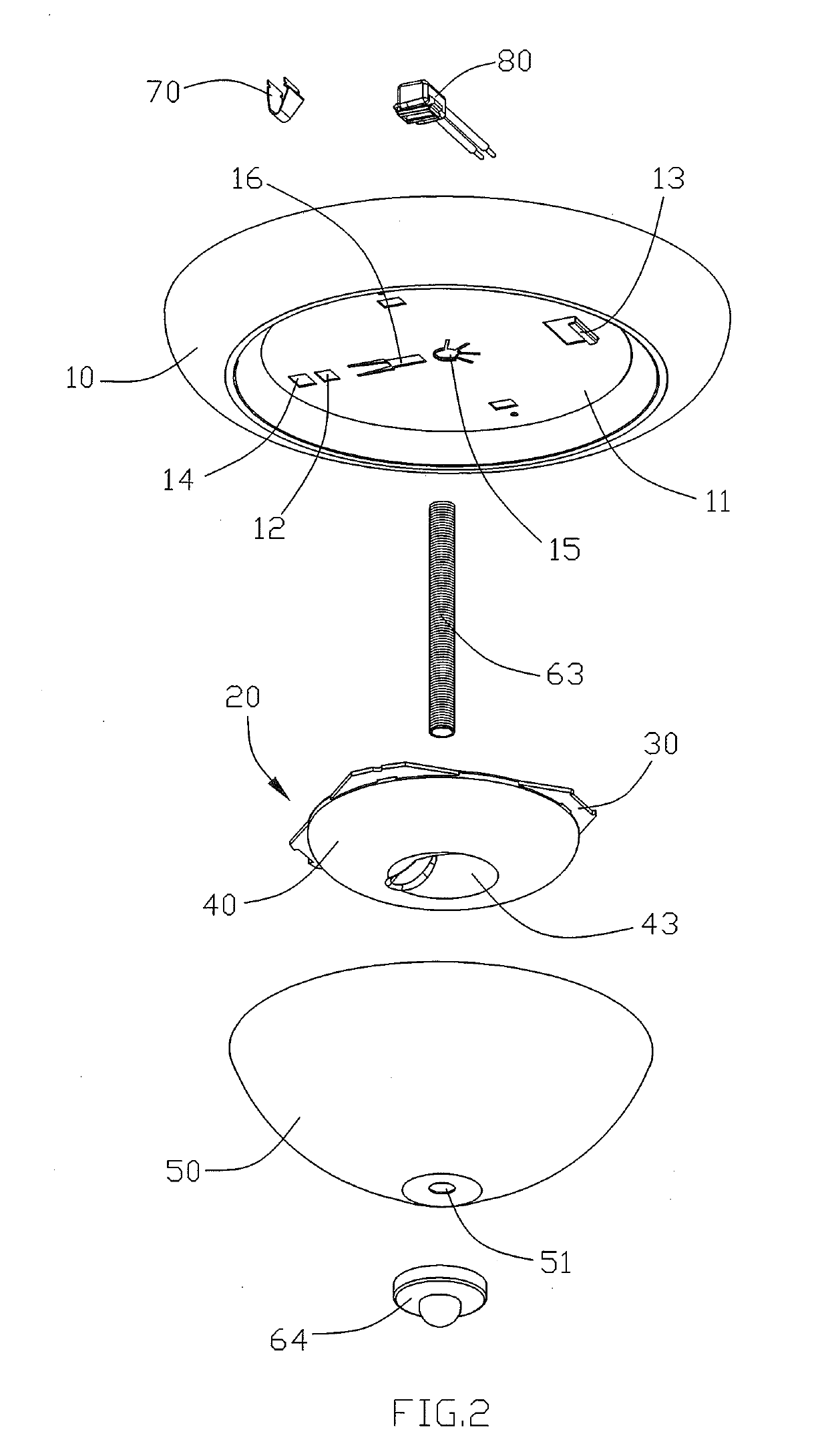
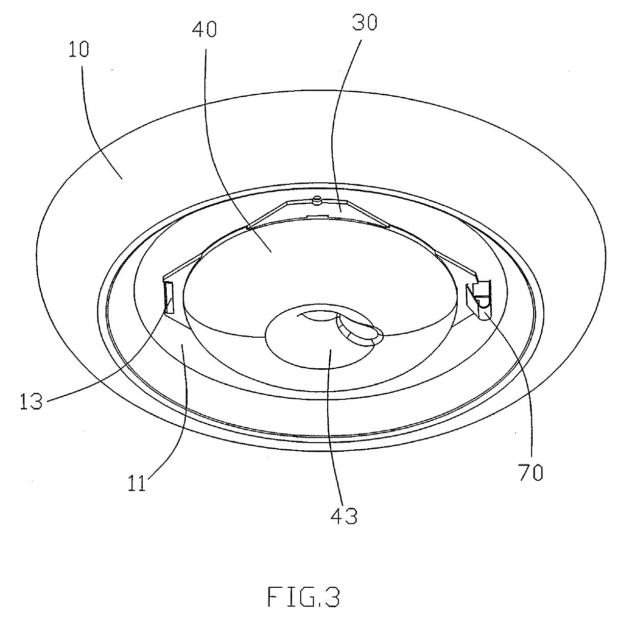
[0017]Referring to FIGS. 1-9, a ceiling fitting in accordance with the preferred embodiment of the present invention comprises a canopy 10, a movable hook 70 mounted on the canopy 10, a lighting module 20 removably mounted on the canopy 10, and an outer cover 50 mounted on the canopy 10 and covering the lighting module 20. The canopy 10 is provided with a fixed hook 13 and a mounting hole 14 located opposite to the fixed hook 13. The movable hook 70 is mounted on the mounting hole 14. The movable hook 70 has a side having a middle position bent outward and forming an arcuate restriction portion 71. The lighting module 20 includes a lamp board 30 mounted on the canopy 10 and located between the movable hook 70 and the fixed hook 13, and a light permeable shell 40 mounted on the lamp board 30. The lamp board 30 has a periphery provided with a first retaining groove 32 and a second retaining groove 33. The first retaining groove 32 is locked onto the movable hook 70, with the restricti...


PUM


Abstract

A ceiling fitting includes a canopy provided with a fixed hook and a mounting hole, a movable hook mounted on the mounting hole of the canopy and having an arcuate restriction portion, a lighting module removably mounted on the canopy, and an outer cover covering the lighting module. The lighting module includes a lamp board mounted on the canopy and located between the movable hook and the fixed hook, and a light permeable shell mounted on the lamp board. The lamp board is provided with a first retaining groove and a second retaining groove. The first retaining groove is locked onto the movable hook, with the restriction portion of the movable hook being retained by the first retaining groove of the lamp board. The second retaining groove is locked onto the fixed hook.

Description

BACKGROUND OF THE INVENTION1. Field of the Invention[0001]The present invention relates to a lighting device and, more particularly, to a ceiling fitting.2. Description of the Related Art[0002]A ceiling fitting is mounted on a ceiling (or wall) to provide a lighting function. A conventional ceiling fitting comprises a light source which uses an LED instead of the E27 bulb. The conventional ceiling fitting further comprises a canopy, an aluminum base plate and a protective cover. The canopy is attached to the ceiling. The aluminum base plate and the protective cover are secured to the canopy by screws. However, the light source and the canopy are combined integrally and cannot be replaced or repaired individually, so that it is necessary to replace the whole ceiling fitting when the light source or the canopy is worn out, thereby increasing the cost.BRIEF SUMMARY OF THE INVENTION[0003]In accordance with the present invention, there is provided a ceiling fitting comprising a canopy, a...

Claims


Application Information

Patent Timeline
IPC IPC(8): F21V21/04F21V21/08F21S8/04F21V17/10
CPCF21V21/047F21V21/0832F21S8/04F21V17/108F21Y2115/10H01R13/4362H01R12/7023H01R12/57H01R13/24F21V21/03F21V17/12F21V23/005F21S8/043H01R4/48185
Inventor HSU, KEVIN
Owner DONG GUAN BRIGHT YIN HUEY LIGHTING
Why Eureka
Try Eureka