Check patentability & draft patents in minutes with Patsnap Eureka AI!

Command control system, interceptor system, and command control method

Active Publication Date: 2019-08-15
MITSUBISHI HEAVY IND LTD
View PDF0 Cites 4 Cited by
  • Summary
  • Abstract
  • Description
  • Claims
  • Application Information

AI Technical Summary

Benefits of technology

The present invention aims to provide an interceptor system that can be used for any weather condition and has low running costs. This is achieved by determining the guided missile used for interception based on weather data. The use of infrared seeker for guiding flying objects is costly, so the invention proposes the use of a radio frequency seeker which is more affordable. Overall, the invention provides a cost-effective solution for interception systems.

Problems solved by technology

However, the flying object using a radio frequency seeker requires high cost, compared with the flying object using an infrared seeker.

Method used


Image

  • Command control system, interceptor system, and command control method
  • Command control system, interceptor system, and command control method
  • Command control system, interceptor system, and command control method

Examples


embodiment 1

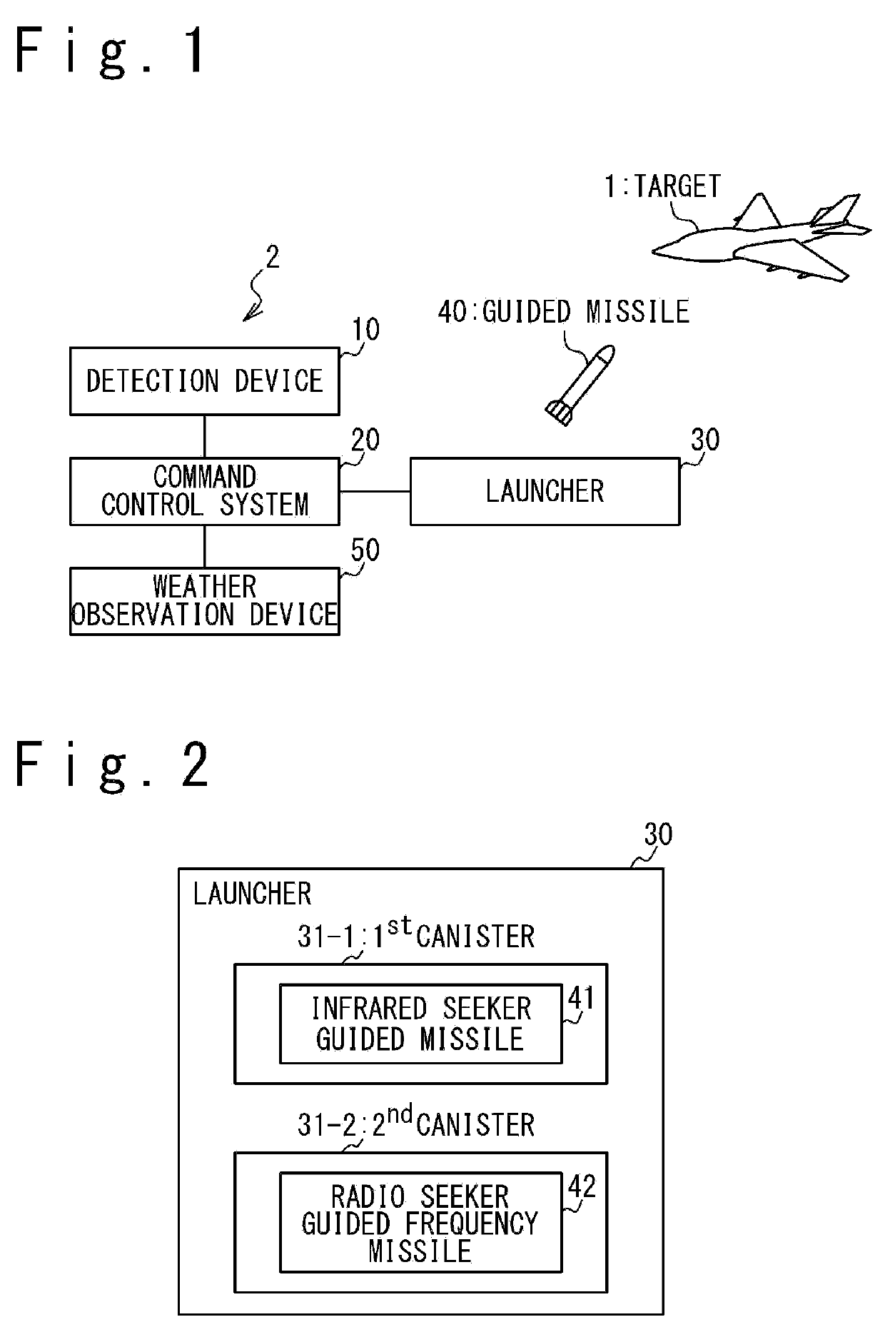
[0041]An interceptor system 2 according to an embodiment 1 contains a detection device 10, a command control system 20, a launcher 30, a guided missile 40 and a weather observation device 50, as shown in FIG. 1. The command control system 20 is connected with the detection device 10, the launcher 30 and the weather observation device 50. The detection device 10 detects a target 1 to be shot down. The weather observation device 50 observes weather in the neighborhood. The command control system 20 determines the guided missile 40 suitable to intercept the target 1 based on the detected target 1 and weather data observed by the weather observation device 50. The launcher 30 launches the determined guided missile 40 for the target 1. The guided missile 40 is an infrared seeker guided missile 41 or a radio frequency seeker guided missile 42.

[0042]As shown in FIG. 2, the launcher 30 has a plurality of canisters 31 which contain a first canister 31-1 and a second canister 31-2. The infrar...

embodiment 2

[0062]In the embodiment 1, an example has been shown in which the kind of guided missile 40 is determined based on the weather data in the predicted intercept point 200. As shown in FIG. 7, even if the predicted intercept point 200 is fair, there is a case that a first guided missile route 300-1 passes through the rainfall region 500. In such a case, if the infrared seeker guided missile 41 is launched, there is a possibility that the infrared seeker breaks down in the rainfall region 500. Therefore, in an embodiment 2, an example is shown in which the interceptor system 2 searches a second guided missile route 300-2 bypassing the rainfall region 500. If the second guided missile route 300-2 can be searched, the infrared seeker guided missile 41 is launched to fly along the second guided missile route 300-2. In this way, the interceptor system 2 can change the kind of guided missile 40 to be launched, based on the weather data along the guided missile route 300.

[0063]The functional ...

embodiment 3

[0079]As shown in FIG. 10, a case can be supposed where the predicted intercept point 200 is contained in the rainfall region 500 and there is a fair area 510 in the neighborhood of the predicted intercept point 200. In this case, the launching timing of the guided missile 40 may be adjusted so that the intercept point is changed into the fair area 510. In other words, by changing the intercept point, the infrared seeker guided missile 41 is launched so that the target 1 can be shot down. Thus, the interceptor system 2 searches whether or not the fair area 510 is present in the neighborhood of the predicted intercept point 200. When the fair area 510 is present, the intercept point is changes and the infrared seeker guided missile 41 is launched.

[0080]The functional configuration of the interceptor system 2 will be described. Each of the detection device 10, the launcher 30, the guided missile 40 and the weather observation device 50 has the same function as in the embodiment 2.

[008...


PUM


Abstract

A command control system includes an interception predicting section and an assigning section. The interception predicting section calculates a predicted intercept point of a target to be shot down and a guided missile to shoot down the target. The assigning section acquires first weather data of the predicted intercept point, and generates a launching instruction based on the first weather data so as to launch one of a first guided missile and a second guided missile as the guided missile. A method by which the first guided missile detects the target and a method by which the second guided missile detects the target are different.

Description

TECHNICAL FIELD[0001]The present invention relates to a command control system, an interceptor system, and a command control method.BACKGROUND ART[0002]There is a method of detecting a target such as a flying object and guiding a missile for the target by using an infrared seeker.[0003]Patent Literature 1 discloses a technique of guiding a flying object by comparing an image picked up by an infrared image pickup device and an image produced based on landform data and weather data.[0004]Patent Literature 2 discloses a technique of determining whether a flying object can fly to a target point based on landform data, launching factors of the flying object and inputted weather data.[0005]Patent Literature 3 discloses a technique of calculating a flying object route based on weather data. Also, Patent Literature 3 discloses a technique of the flying object flying above a rainfall region when the flying object detects the rainfall region.CITATION LIST[0006][Patent Literature 1] JP H08-285...

Claims


Application Information

Patent Timeline
IPC IPC(8): F41G7/34F42B15/01G01S13/88G01S3/782G05D1/12
CPCF41G7/34F42B15/01G01S13/88G01S3/782G05D1/12G01S13/883F41G7/007F41G7/2233F41G7/2286F41G7/2293
Inventor ANDO, KEISUKE
Owner MITSUBISHI HEAVY IND LTD
Features
  • R&D
  • Intellectual Property
  • Life Sciences
  • Materials
  • Tech Scout
  • Unparalleled Data Quality
  • Higher Quality Content
  • 60% Fewer Hallucinations
Learn More