Vehicle and electric power control device for vehicle

a technology for electric power control devices and vehicles, which is applied in the direction of electric devices, battery/fuel cell control arrangements, electric devices, etc., can solve the problems of excessively limited charge power, excessive dc charge, and high so as to shorten the time required for dc charge and increase the maximum output of dc charging devices , the effect of increasing the temperature of current-carrying components and shortening the time required

Active Publication Date: 2019-08-15
TOYOTA JIDOSHA KK
View PDF0 Cites 4 Cited by
  • Summary
  • Abstract
  • Description
  • Claims
  • Application Information

AI Technical Summary

Benefits of technology

[0005]In recent years, for shortening the time required for the DC charge, the maximum output of the DC charging device has been increased compared to the related art. In connection with this, there has been developed a DC charging device in which the possible output current value (a maximum output current value) is set to a value (for example, about several hundred amperes) significantly higher than a conventional value (for example, about several dozen amperes). Accordingly, hereafter, DC charging devices having different possible output current values can coexist in the market.
[0006]In a vehicle that supports the DC charge using the DC charging device in which the possible output current value is increased compared to the related art, a charge current that is supplied from the DC charging device to the vehicle can be significantly increased compared to the related art. In the current-carrying component through which the charge current flows, a Joule heat proportional to the square of the current value is generated, and therefore, the increase rate of the temperature of the current-carrying component can be remarkably increased compared to the related art.

Problems solved by technology

When the calculated evaluation value (the temperature of the current-carrying component) exceeds a threshold (constant value), the upper limit value of charge power for the electric storage device is limited.
Therefore, in the case where the charge current is high, there is a concern that the temperature of the current-carrying component continues to increase for a while even after the charge current starts to be limited, so that the temperature of the current-carrying component exceeds a permissible temperature.
However, there is a concern that the charge power is excessively limited, so that the DC charge cannot be appropriately performed.
On the other hand, for example, when the possible output current value of the charging device is low, the threshold can be altered such that the current limitation is hard to be performed, in consideration of the fact that the heat quantity to be generated in the current-carrying component is not very high.
Therefore, as the possible output current value is higher, the temperature of the current-carrying component exceeds the threshold more easily, and the current limitation by the current limiting process is started earlier.

Method used


Image

  • Vehicle and electric power control device for vehicle
  • Vehicle and electric power control device for vehicle
  • Vehicle and electric power control device for vehicle

Examples


first modification

[0089

[0090]In the example described in the above embodiment, the DC inlet temperature Ti detected by the temperature sensor 194 is monitored in the current limiting process.

[0091]However, the DC inlet temperature Ti is not necessarily limited to the detection by the sensor. For example, the DC charge time and the charge current may be adopted as parameters in the calculation of the DC inlet temperature Ti.

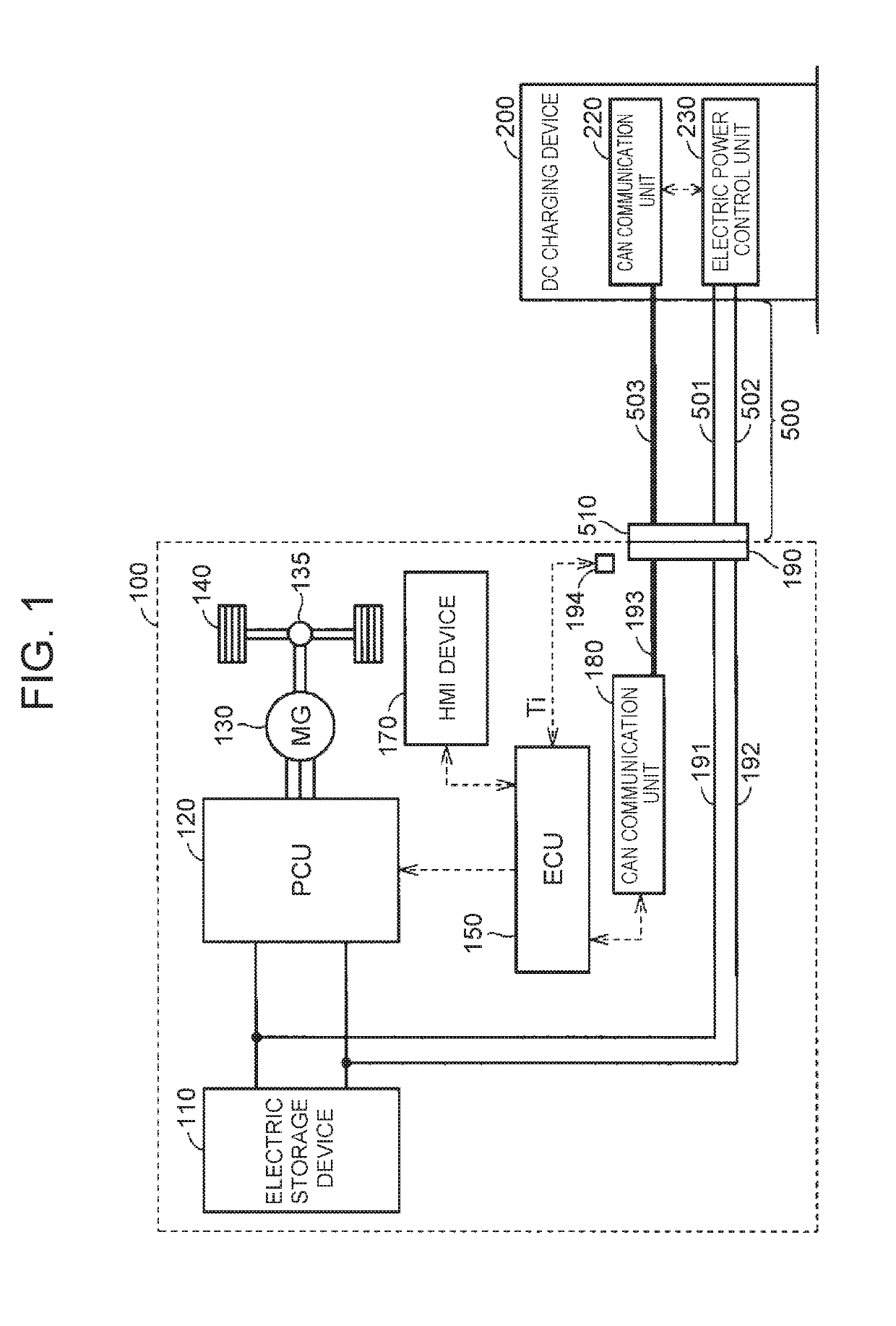
[0092]Further, the object to be monitored in the current limiting process is not necessarily limited to the DC inlet temperature Ti. For example, in the case where there is a current-carrying component that is weak against heat, other than the DC inlet 190, in the circuit through which the charge current flows, the temperature of the current-carrying component may be monitored instead of or in addition to the DC inlet 190.

second modification

[0093

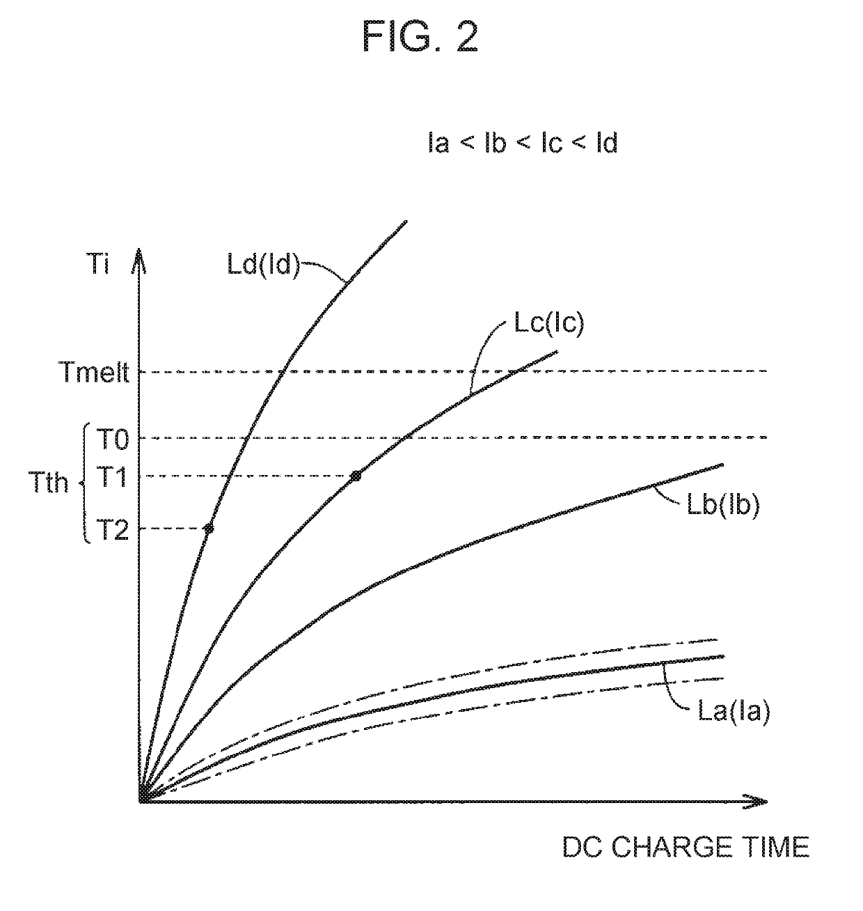
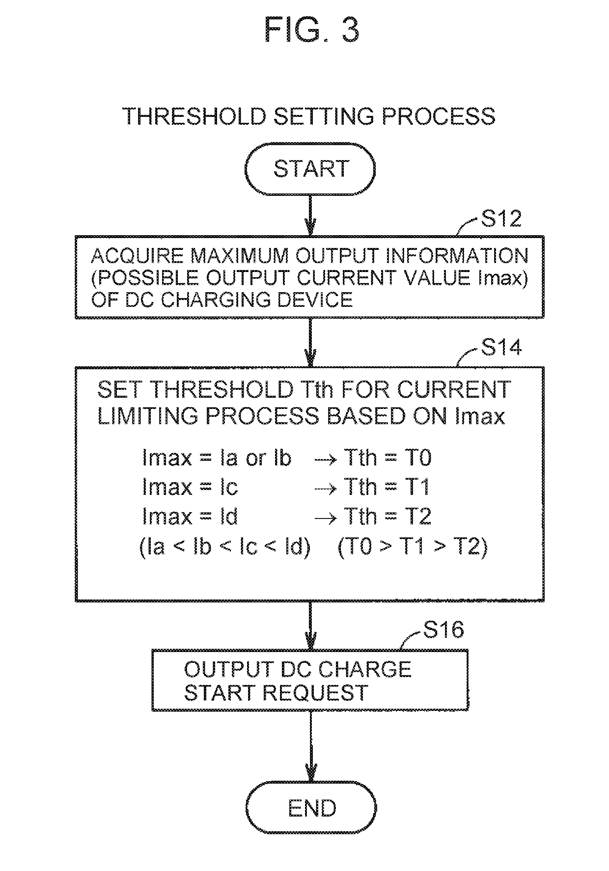
[0094]In the example described in the above embodiment, the DC inlet temperature Ti is used as the parameter relevant to the temperature of the DC inlet 190 (current-carrying component). Specifically, in the example, in the current limiting process, the charge current is limited when the DC inlet temperature Ti exceeds the threshold Tth. Further, in the example, in the threshold setting process, the threshold Tth that is used in the current limiting process is set to a lower value, as the possible output current value Imax of the DC charging device 200 is higher.

[0095]On the other hand, in an example that will be described in the modification, an increase rate (hereinafter. also referred to as a “DC inlet temperature increase rate ΔTi”) of the DC inlet temperature Ti is used as the parameter relevant to the temperature of the DC inlet 190 (current-carrying component). Specifically, in the example, in the current limiting process, the charge current is limited when the DC inlet ...

third modification

[0113

[0114]The temperature increase characteristic of the DC inlet temperature Ti in the DC charge can change due to a deterioration, a poor contact or the like at the contact portion between the DC charge connector 510 and the DC inlet 190.

[0115]FIG. 8 is a diagram showing an exemplary change in the temperature increase characteristic of the DC inlet temperature Ti in the DC charge. A curve Ld shown in FIG. 8 is the same as the curve Ld shown in FIG. 2 and FIG. 5 described above. That is, the curve Ld is a curve showing the change in the DC inlet temperature Ti when the charge current is the predetermined value Id.

[0116]In the case where a deterioration, a poor contact or the like does not occur at the contact portion between the DC charge connector 510 and the DC inlet 190, it is assumed that the DC inlet temperature Ti increases along the curve Ld.

[0117]However, in the case where a deterioration, a poor contact or the like occurs at the contact portion between the DC charge conne...


PUM


Abstract

An electric power control device for a vehicle which is configured to receive direct current which is supplied from a charging device outside the vehicle and includes an electric storage device configured to be charged by the direct current includes an electronic control unit configured to: acquire maximum output information of the charging device; while the electric storage device is charged by the direct current supplied from the charging device, execute a current limiting process in which the direct current becomes lower than a predetermined value when a parameter relevant to a temperature of a current-carrying component and a threshold of the parameter satisfy a predetermined condition, the current-carrying component being a component in which the direct current flows through; and set the threshold based on the maximum output information of the charging device.

Description

CROSS-REFERENCE TO RELATED APPLICATIONS[0001]This application claims priority to Japanese Patent Application No. 2018-023397 filed on Feb. 13, 2018, which is incorporated herein by reference in its entirety including the specification, drawings and abstract.BACKGROUND1. Technical Field[0002]The disclosure relates to a vehicle and an electric power control device for a vehicle capable of receiving direct current that is supplied from a charging device outside the vehicle.2. Description of Related Art[0003]Japanese Patent Application Publication No. 2014-45541 (JP 2014-45541 A) discloses an electric vehicle including an electric storage device. In this vehicle, an evaluation value indicating the temperature of a component (hereinafter referred to as “current-carrying component”) which is used to carry current and is connected to the electric storage device is calculated based on a current value that is detected at the time of charge of the electric storage device. When the calculated ...

Claims


Application Information

Patent Timeline
Patent Type & Authority Applications(United States)
IPC IPC(8): H02J7/04H02J7/14B60L53/63B60L58/12
CPCH02J7/047H02J7/1453B60L53/63B60L58/12B60L3/00B60L53/14B60L50/51B60L53/11B60L53/66B60L53/62Y02T90/16Y02T90/12Y02T10/70Y02T10/7072Y02T90/14H02J7/007192
Inventor KUSUMI, HIDETOSHI
Owner TOYOTA JIDOSHA KK
Why Eureka
Try Eureka