Portable spirometer

a spirometer and portability technology, applied in the field of portable spirometers, can solve the problems of no parameters, no device can store a limited number of measurements, and severe low lung function, and may not generate any sound

a spirometer and portability technology, applied in the field of portable spirometers, can solve the problems of no parameters, no device can store a limited number of measurements, and severe low lung function, and may not generate any sound

US20190254534A1Active Publication Date: 2019-08-22HEALTHUP SP ZOO

Image

  • Portable spirometer
  • Portable spirometer
  • Portable spirometer

Examples


Embodiment Construction

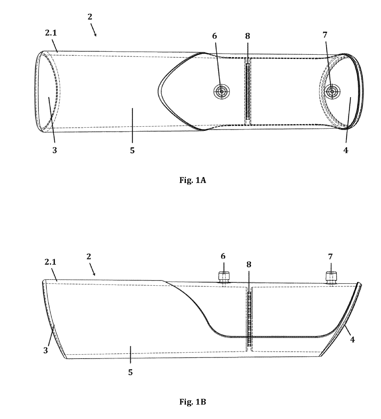
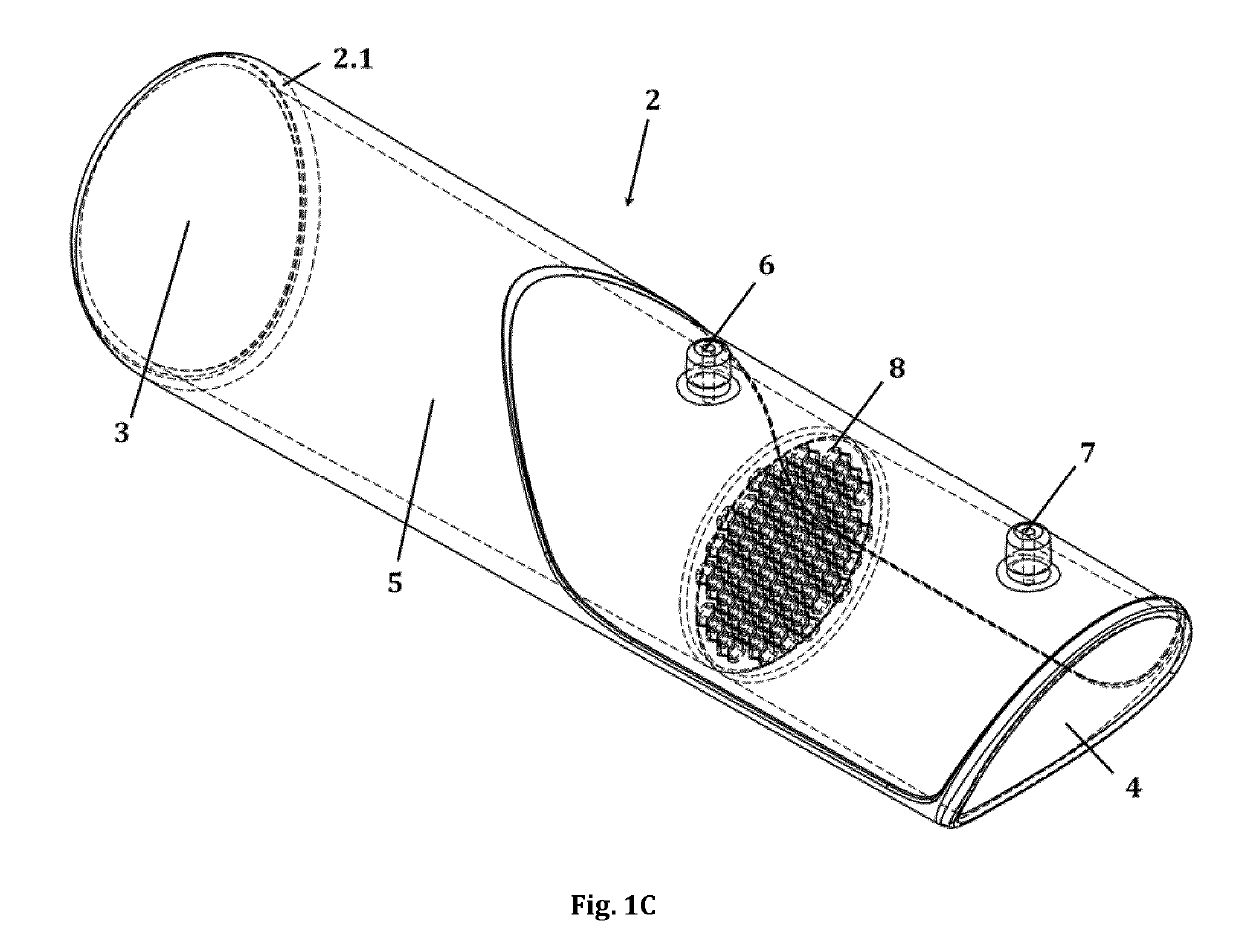
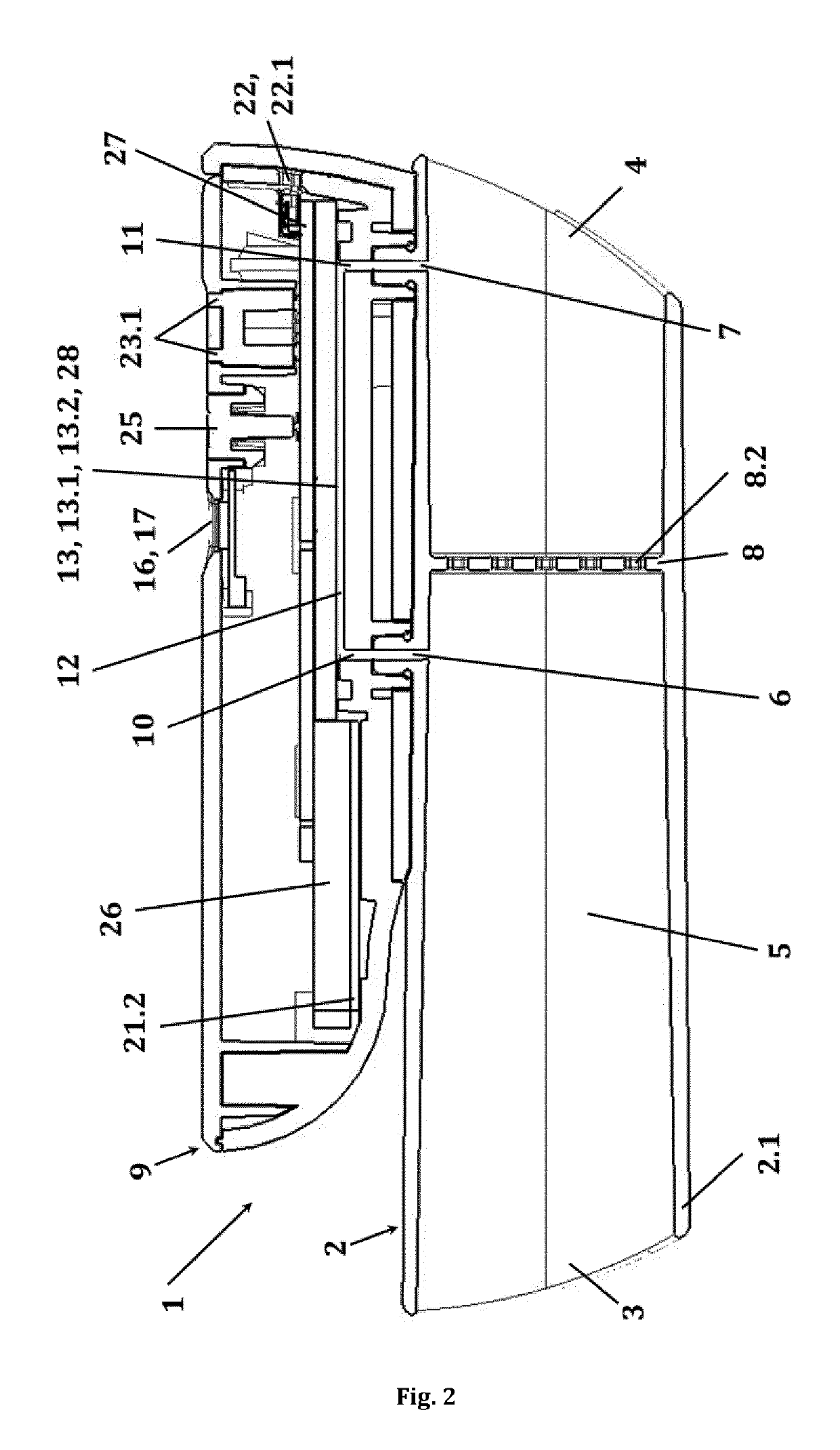
[0056]In a first aspect, the invention provides a portable electronic spirometer (1) comprising (a) a tubular mouthpiece (2) with a proximal opening (3) for insertion into the mouth of a user, a distal opening (4), a main fluid channel (5) extending between the proximal opening (3) and the distal opening (4), a first lateral opening (6), a second lateral opening (7) positioned at a longitudinal distance to the first, and a flow restrictor (8) positioned in the main fluid channel (5) between the first and the second lateral opening (6 and 7); and

[0057](b) a main body (9) with a first fluid opening (10) connectible with the first lateral opening (6) of the mouthpiece (2), a second fluid opening (11) connectible with the second lateral opening (7) of the mouthpiece (2), a bypass fluid channel (12) extending between the first and the second fluid opening (10 and 11), a MEMS-based thermal fluid flow sensor (13) which is positioned at the bypass fluid channel (12) for generating a signal ...


PUM


Abstract

The invention relates to a spirometer (1) comprising a MEMS-based thermal fluid flow sensor (13, 13.1, 13.2) for generating a signal in response to a fluid flow generated during inhalation or exhalation; and a microcontroller (14) for calculating the fluid flow from the signal generated by the flow sensor (13, 13.1, 13.2). The spirometer (1) may be connected to other devices, such as a smartphone or a personal computer or any other computing unit which is adapted to collect, store, analyse, exchange and / or display data. The invention further describes the use of the spirometer (1) in measuring a user's lung performance and / or monitoring it over time. Furthermore, the spirometer (1) may be provided in a system together with an air quality measurement device for determining the air quality at a location of interest; and a computing unit for collecting, analysing and correlating the user's lung performance data obtained from the spirometer (1) with the air quality data, and optionally geolocalisation data of said location.

Description

BACKGROUND OF THE INVENTION[0001]The invention is related to a portable spirometry device, or spirometer, as well as a method for determining lung function parameters using said device.[0002]Spirometry is one of the most common tests used for determining, or evaluating, pulmonary function in terms of lung function parameters relating to the amount (volume) and / or speed (flow, or flow rate) of air that can be inhaled and exhaled, either forcedly or under normal breathing. The primary signals measured in spirometry may be volume and / or flow. Results are provided both as raw data (litres, litres per second) and as percent predicted, i.e. in relation to predicted values for patients of similar parameters such as height, age, sex, weight and sometimes ethnicity. Since multiple publications of predicted values are available, the interpretation of the results may vary slightly, but generally speaking, results close to 100% predicted are the most normal, and results ≥80% are usually also co...

Claims


Application Information

Patent Timeline
22 Aug 2019
Publication
US20190254534A1
IPC
A61B5/0205; A61B5/087; A61B5/1455; A61B5/00; G01F1/68; G01F1/44
CPC
A61B5/0205; A61B5/087; A61B5/14552; A61B5/0002; G01F1/68; G01F1/44; A61B5/02438; A61B2560/0252
Inventors
KOLTOWSKI, LUKASZ; BAJTALA, PIOTR