
Built-in roller shade actuation device

a technology of actuation device and roller shade, which is applied in the direction of door/window protective device, mechanical apparatus, gearing, etc., can solve the problems of difficult effective control of generated elastic force, prone to unevenness, and relatively complicated structures, and achieve the effect of smooth driving of roller shad

Active Publication Date: 2019-08-22
LEAFY WINDOWARE CO LTD
View PDF0 Cites 4 Cited by
  • Summary
  • Abstract
  • Description
  • Claims
  • Application Information

AI Technical Summary

Benefits of technology

The technical effect of this patent is that it provides an internal mechanism for controlling the movement of a window covering called a roller shade. This allows for easy retraction or release of the shade without causing any issues with its operation.

Problems solved by technology

The technical problem addressed in this patent relates to improving the design of springs for window blinds/curts. Current designs have issues with evenness and difficulty controlling elastic force, leading to expensive and complex solutions.

Method used


Image

  • Built-in roller shade actuation device
  • Built-in roller shade actuation device
  • Built-in roller shade actuation device

Examples


Embodiment Construction

[0021]The present application will be further described in detail below with reference to the accompanying drawings and specific embodiments. It should be understood that the following illustrative embodiments and illustrations are only used to explain the present invention and are not intended to limit the invention, and that the embodiments of the present invention and the features of the embodiments can be combined with each other without conflict.

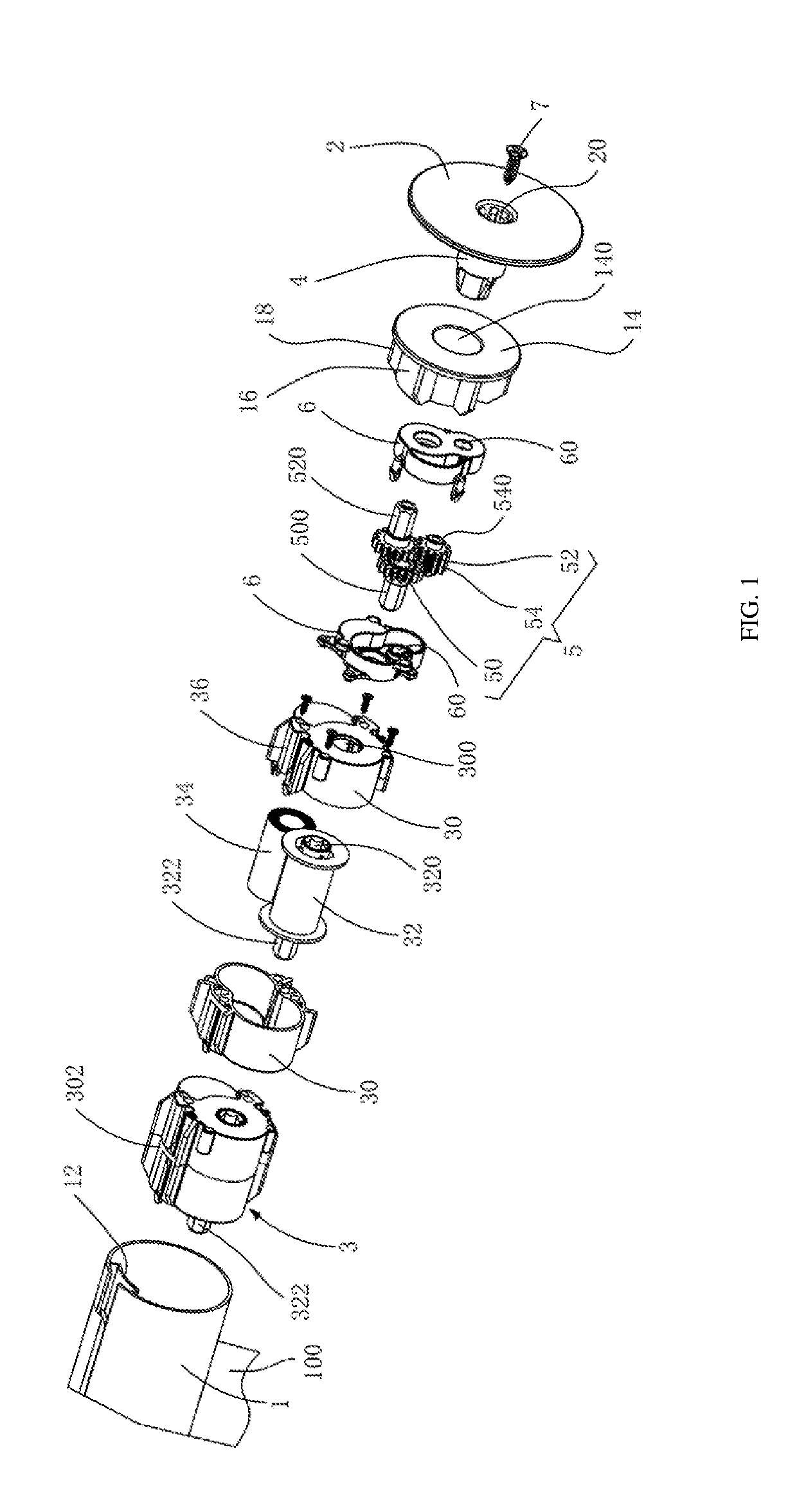
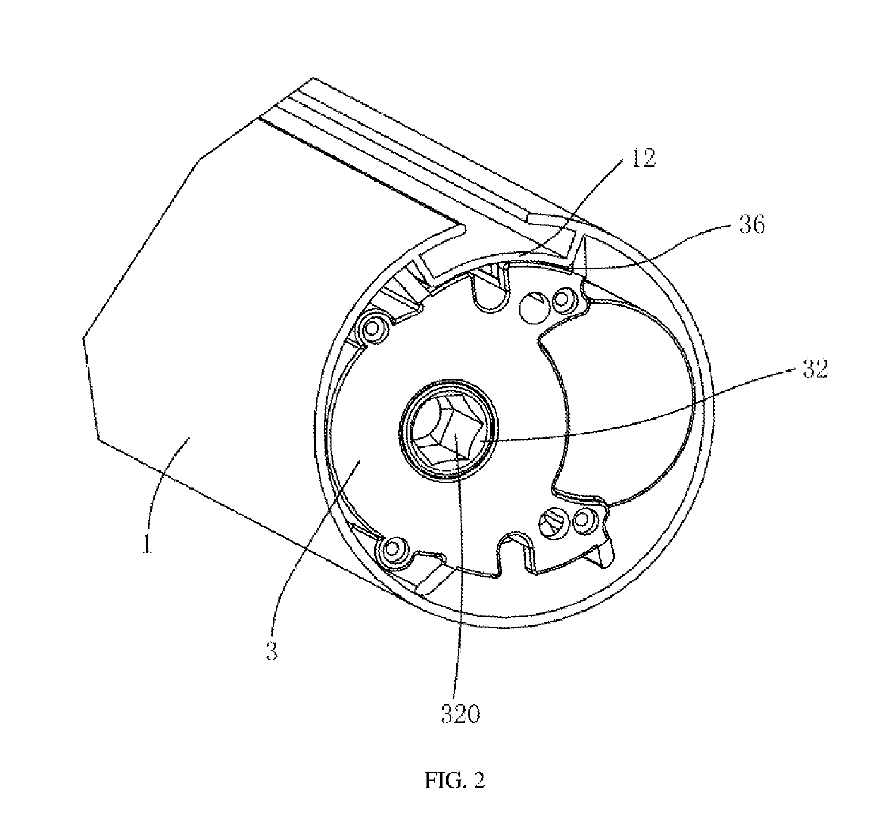
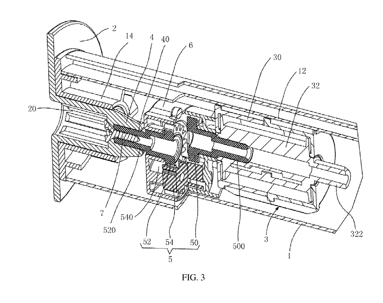
[0022]Referring to FIGS. 1-3, an embodiment of the present disclosure provides a built-in roller shade actuation device for actuating a winding drum 1 with opposite ends rotatably mounted to corresponding frames 2 and an outer side mounted with an end of a shade body 100. The built-in roller shade actuation device includes an actuator 3 assembled in the winding drum 1 for providing a rotation power, a shaft 4 mounted to one of the frames 2 outside an end of the winding drum 1 and inserted into the winding drum 1, and a gear pair 5 mount...


PUM


Abstract

A built-in roller shade actuation device for actuating a winding drum with opposite ends rotatably mounted to corresponding frames and an outer side mounted with an end of a shade body includes an actuator assembled in the winding drum for providing a rotation power, a shaft mounted to one of the frames outside an end of the winding drum and inserted into the winding drum, and a gear pair mounted between the actuator and the shaft for realizing power transmission. A shell of the actuator and the winding drum are relatively fixed in a circumferential direction. The gear pair includes a planetary gear mounted to an output shaft of the actuator, and a fixed gear mounted to the shaft and coaxial with the winding drum. The planetary gear revolves around the fixed gear while being driven to rotate by the output shaft of the actuator.

Description


Claims


Application Information

Patent Timeline
Owner LEAFY WINDOWARE CO LTD
Learn More