
Calibration apparatus for onboard camera and calibration method for onboard camera

a technology of calibration method and onboard camera, which is applied in the field of calibration apparatus for onboard camera and calibration method for onboard camera, can solve the problems of large space required for calibration to be performed, and significant amount of labor for numerous markers to be provided, so as to reduce the number of markers provided on the floor surface in advance, accurately measure, and accurately calculate the distance between the same markers imaged at different times in the specific image

Active Publication Date: 2019-08-22
DENSO CORP
View PDF0 Cites 2 Cited by
  • Summary
  • Abstract
  • Description
  • Claims
  • Application Information

AI Technical Summary

Benefits of technology

The present patent provides a calibration apparatus and method for an onboard camera that can reduce the number of markers on a floor surface. The apparatus stores multiple images of markers with different relative positions from the perspective of the vehicle. This eliminates the need for markers on the floor surface and improves the accuracy of the calibration. The apparatus calculates the movement distance of the vehicle based on the repeated movement of the markers in the images. This allows accurate measurement of the distance between the same markers in the images, and further improves the accuracy of the calibration.

Problems solved by technology

Therefore, a large space is required for calibration to be performed.
Furthermore, a significant amount of labor is required for numerous markers to be provided.

Method used


Image

  • Calibration apparatus for onboard camera and calibration method for onboard camera
  • Calibration apparatus for onboard camera and calibration method for onboard camera
  • Calibration apparatus for onboard camera and calibration method for onboard camera

Examples


first embodiment

1. Configuration of a Calibration Apparatus 1

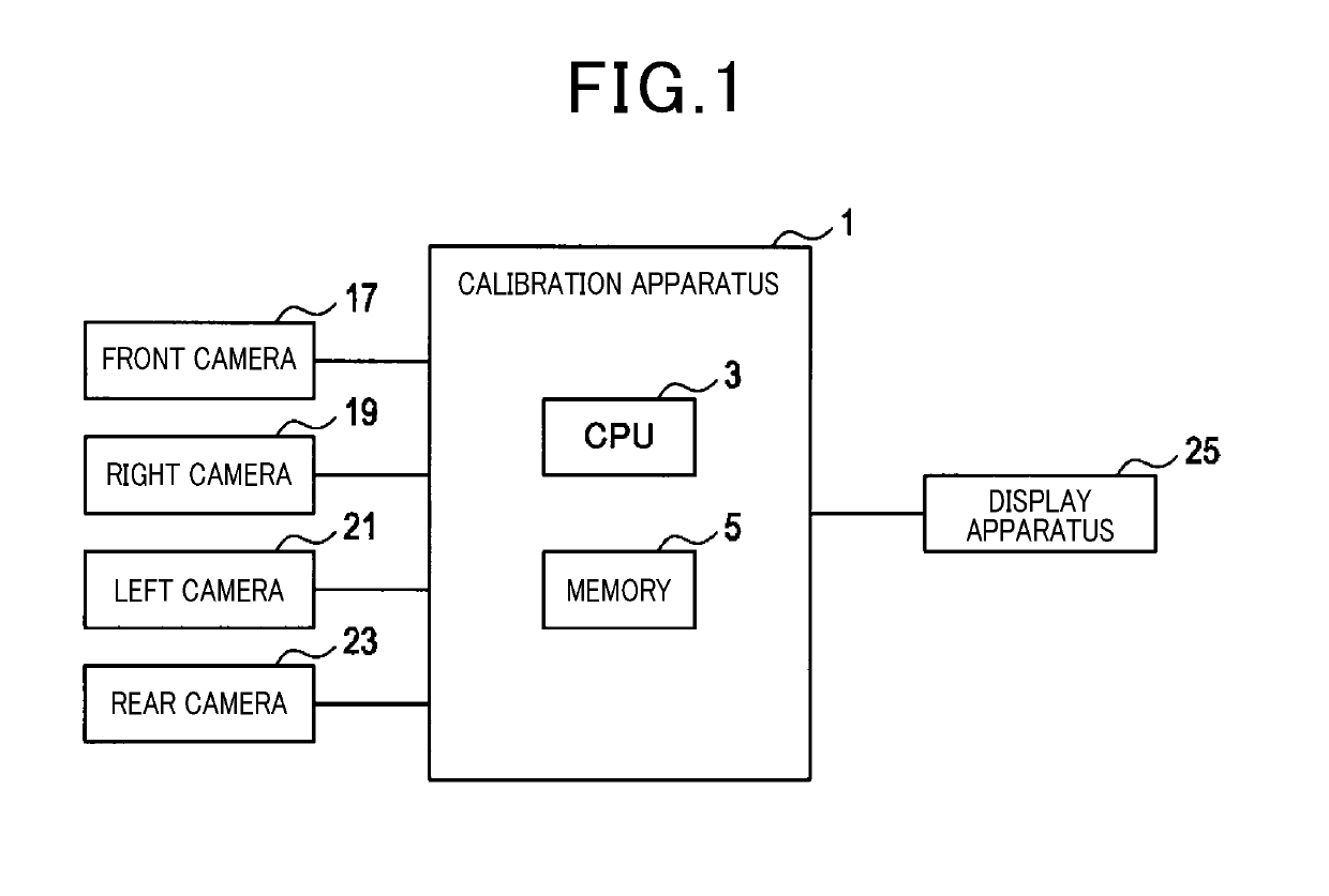
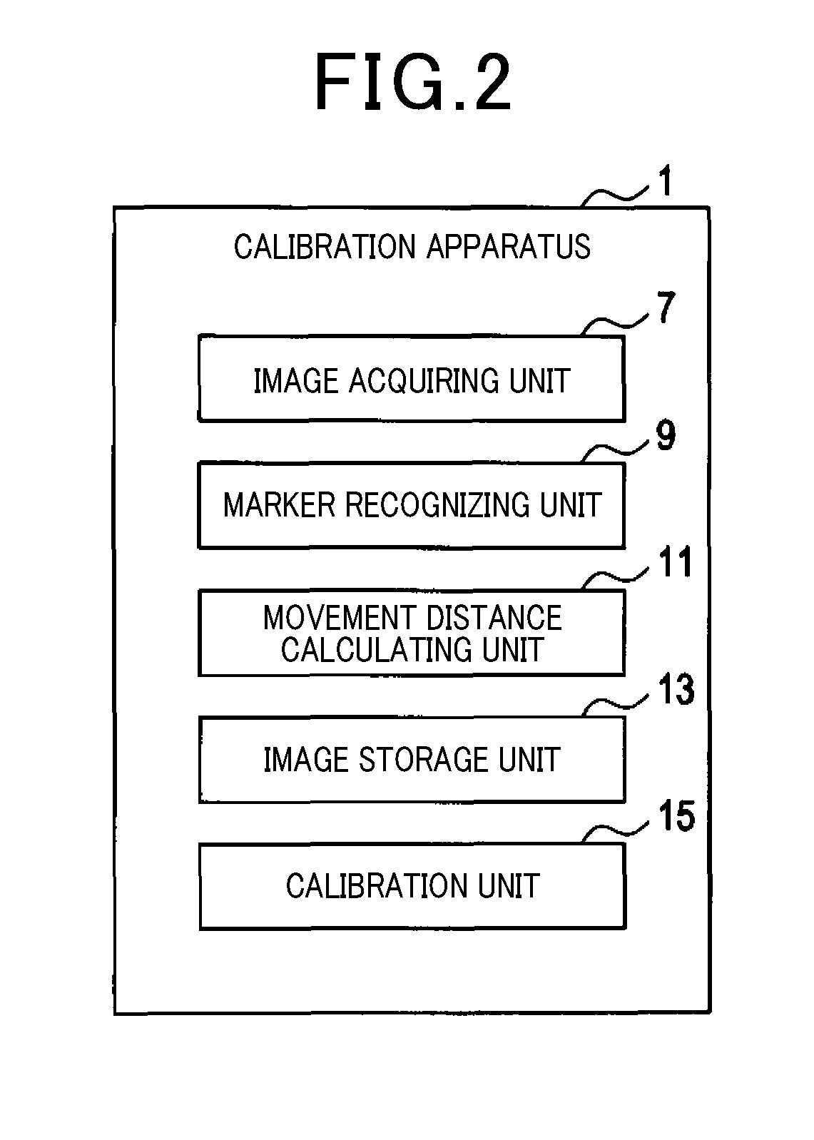
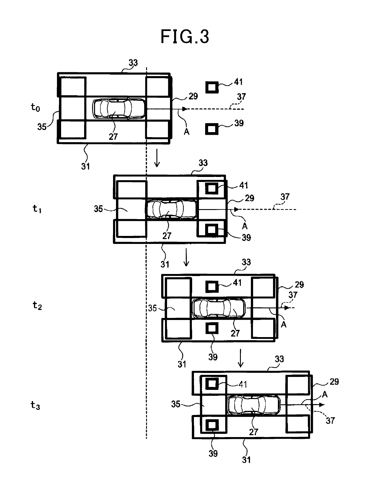
[0037]A configuration a calibration apparatus 1 will be described with reference to FIG. 1 to FIG. 3. The calibration apparatus 1 is an apparatus that performs calibration of an onboard camera. A vehicle in which the onboard camera is mounted is hereinafter referred to as an own vehicle. The calibration apparatus 1 may be mounted in the own vehicle. Alternatively, the calibration apparatus 1 may be set in a location other than the own vehicle.

[0038]As shown in FIG. 1, the calibration apparatus 1 is mainly configured by a known microcomputer that includes a central processing unit (CPU) 3, a random access memory (RAM), a read-only memory (ROM), and a semiconductor memory (hereinafter referred to as a memory 5) such as a flash memory. Various functions of the calibration apparatus 1 are actualized by the CPU 3 running a program that is stored in a non-transitory computer-readable storage medium. In this example, the memory 5 corresponds to ...


PUM


Abstract

A calibration apparatus for an onboard camera includes an image acquiring unit, a marker recognizing unit, a movement distance calculating unit, an image storage unit, and a calibration unit. The movement distance calculating unit calculates a movement distance of a vehicle based on a number of times that a process in which a first feature portion in a marker moves to a position overlapping a second feature position in the marker in the image is repeated. The image storage unit stores a specific image that includes the marker. The calibration unit calibrates the onboard camera using the specific image. The image storage unit stores, as the specific image, (a) the image in which the marker is recognized, and (b) the image acquired when the movement distance from a position of the vehicle when the specific image has been acquired in the past reaches a predetermined distance.

Description

CROSS-REFERENCE TO RELATED APPLICATIONS[0001]The present international application claims the benefit of priority based on Japanese Patent Application No. 2016-203640, filed on Oct. 17, 2016 to the Japan Patent Office, the descriptions of which are incorporated herein by reference.TECHNICAL FIELD[0002]The present disclosure relates to a calibration apparatus for an onboard camera and a calibration method for an onboard camera.BACKGROUND ART[0003]Conventionally, a method in which an image of a marker that is provided on a floor surface is captured through use of an onboard camera, and an attitude or the like of the onboard camera is calibrated through use of the acquired image is known. As such a calibration method, there is a method disclosed in PTL 1.CITATION LISTPatent Literature[0004][PTL 1] Japanese Patent Publication No. 4555876SUMMARY OF INVENTION[0005]A following issue has been found as a result of detailed study by the inventors. In the calibration method for an onboard came...

Claims


Application Information

Patent Timeline
Patent Type & Authority Applications(United States)
IPC IPC(8): G06T7/80G01B11/26G06T1/00H04N17/00H04N5/225H04N7/18
CPCG06T7/80G01B11/26G06T1/0007H04N17/002H04N5/225H04N7/18G06T2207/30252G06T2207/30204H04N17/00G06T1/00H04N23/00G06T7/00
Inventor TANAKA, HITOSHI
Owner DENSO CORP
Learn More