Walking assist device

a technology of assist device and assist device, which is applied in the direction of cardiovascular exercise device, gymnastic exercise, sport apparatus, etc., can solve the problems of not being able to walk at his/her own pace and no drive sour

Active Publication Date: 2019-08-29
JTEKT CORP
View PDF0 Cites 4 Cited by
  • Summary
  • Abstract
  • Description
  • Claims
  • Application Information

AI Technical Summary

Benefits of technology

[0009]It is an object of the present invention to provide a walking assist device that assists a user in performing high-quality walk in which the user swings his / her arms correctly in synchronization with motion of the legs of the user, and that achieves a travel speed that matches the arm swing state and the walking speed which are natural (comfortable) for the user.
[0020]With the walking assist device according to the aspect described above, the drive unit is controlled on the basis of the state of the movable handles (e.g. the position of the movable handles or the speed of movement of the movable handles) which is detected using the grasp portion state detection unit. Thus, the travel speed of the walking assist device is adjusted in accordance with the arm swing state of the user. Thus, it is possible to assist the user in performing high-quality walk in which the user swings his / her arms correctly in synchronization with motion of the legs of the user, and to achieve a travel speed that matches the arm swing state and the walking speed which are natural (comfortable) for the user.

Problems solved by technology

However, the arm swing width with which the user swings his / her arms is fixed, and there is no drive source that drives the wheels and the wheels of the walking cart are driven (rotated) by swing of the arms of the user.
Therefore, the user must forcibly adjust the walking speed or the arm swing speed in order to cause the walking speed of the user himself / herself and the travel speed of the walking cart to coincide with each other, and thus may not be able to walk appropriately at his / her own pace.

Method used


Image

  • Walking assist device
  • Walking assist device
  • Walking assist device

Examples


Embodiment Construction

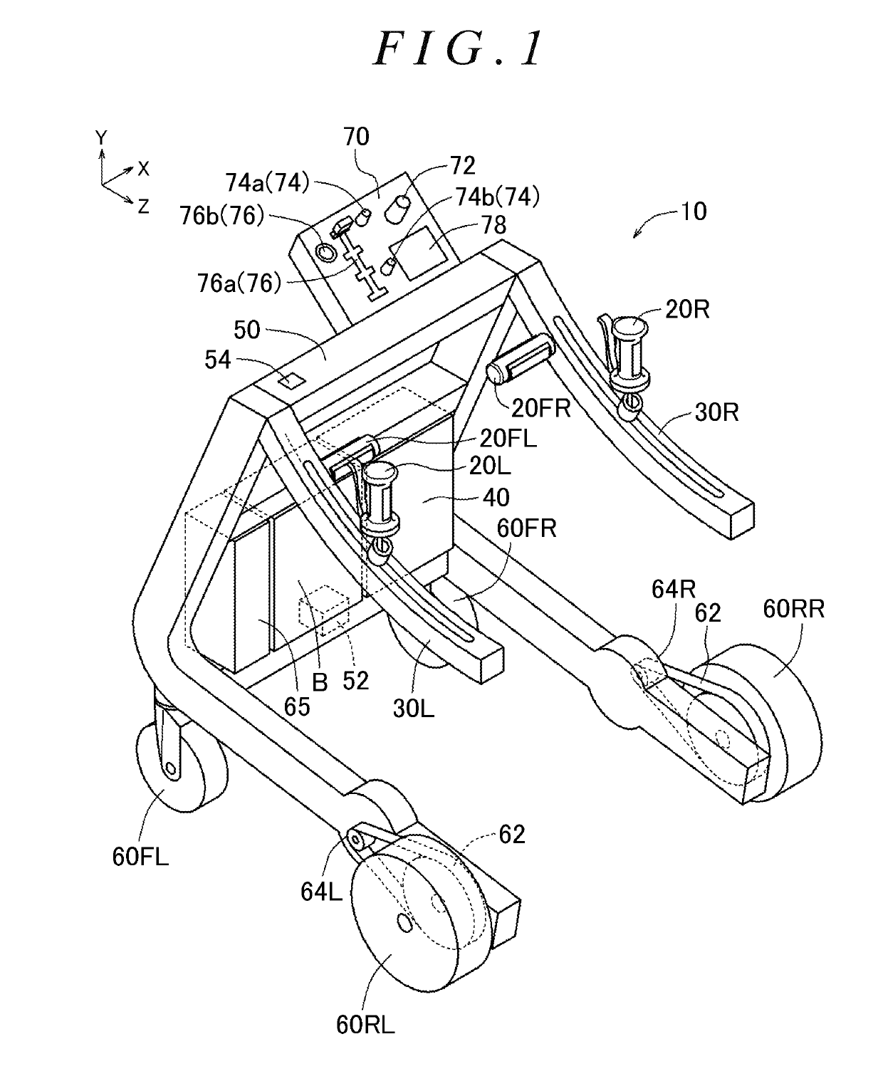
[0050]An embodiment of the present invention will be described below with reference to the drawings. The X axis, the Y axis, and the Z axis in the drawings are orthogonal to each other. In FIG. 1, the Z-axis direction indicates the direction from a front wheel 60FR to a rear wheel 60RR, and the X-axis direction indicates the direction from the left to the right in a frame 50. In the frame 50, the X-axis direction is referred to as “right”, the direction opposite to the X-axis direction is referred to as “left”, the direction opposite to the Z-axis direction is referred to as “front”, and the Z-axis direction is referred to as “rear”. In addition, the Y-axis direction is referred to as “upper”, and the direction opposite to the Y-axis direction is referred to as “lower”. The angular speed for rotation as seen in the X-axis direction is referred to as the pitch angular speed, the angular speed for rotation as seen in the Y-axis direction is referred to as the yaw angular speed, and th...


PUM


Abstract

A walking assist device has a frame, a plurality of wheels, drive units, a battery, and a drive control unit that controls the drive units. The walking assist device also has: a pair of right and left movable handles that are grasped by a user and movable back and forth with respect to the frame in accordance with arm swing performed during walk of the user; handle guide units provided on the frame to guide the movable handles in a movable range that matches the arm swing performed during walk of the user; and a grasp portion state detection unit that detects the state of the movable handles. The drive control unit controls the travel speed of the walking assist device by controlling the drive units on the basis of the state of the movable handles which is detected using the grasp portion state detection unit.

Description

INCORPORATION BY REFERENCE[0001]The disclosures of Japanese Patent Applications No. 2018-33293 and No. 2018-195693 respectively filed on Feb. 27, 2018 and Oct. 17, 2018, each including the specification, drawings and abstract, are incorporated herein by reference in their entireties.BACKGROUND OF THE INVENTION1. Field of the Invention[0002]The present invention relates to a walking assist device.2. Description of Related Art[0003]In order for a user that can walk on his / her own to walk with better quality, it is very important to swing his / her arms correctly in synchronization with his / her legs in a correct posture with his / her body trunk straight without leaning on a walker.[0004]Japanese Patent Application Publication No. 2017-12546 (JP 2017-12546 A), for example, describes a hand cart (corresponding to the walking assist device) that generates an assist force for assisting movement of the hand cart in a travel direction in accordance with the magnitude and the direction of a hand...

Claims


Application Information

Patent Timeline
Patent Type & Authority Applications(United States)
IPC IPC(8): A61H3/04B62B5/06
CPCA61H2201/0176B62B5/0404A61H3/04B62B5/06A61H2003/043A61H2003/046A61H2201/1207A61H2201/5082A61H2201/5084A61H2201/5097A61H2201/5071A61H2201/5069A61H2201/5007B62B5/0069B62B5/004A61H2201/1635A61H1/0277A61H1/0281A61H2201/0173A61H2201/1215A61H2201/1261A61H2201/14A61H2201/1664A61H2201/1669A61H2201/1676A61H2201/5061A61H2201/5064A61H2201/5079A61H2203/0406A61H2205/06A61H2205/065A61H2230/06A61H2230/25A61H2230/50A63B21/0058A63B21/4035A63B21/4045A63B21/4047A63B22/0012A63B22/20A63B23/03516A63B23/03533A63B23/03575A63B23/04A63B23/0405A63B23/12A63B23/1209A63B2022/0094B62B5/0043B62B5/0073B62B3/00
Inventor KANAYA, MANABUSHIBATA, YOSHIYUKITAKEUCHI, SHINJIMURATA, GENKI
Owner JTEKT CORP
Why Eureka
Try Eureka